1 setting the load fault indication, 5 settings – JUMO 709050 IPC IGBT Power Converter IPC 70A Operating Manual User Manual
Page 35
02.08 [IGBT Power Converter 70A]
35
5 Settings
Type: relay
Type:
optocoupler
In the case of a load fault, the floating contact drops out, or the collector-
emitter path of the optocoupler goes high-resistance.
The signal output is also active if the maximum temperature of the converter is
exceeded (overheat) or if the safety cut-out in the power section has been
triggered.
k
factory setting
5.12.1 Setting the load fault indication
h Connect the load
h Provide a full control signal (e.G. 20 mA at the control input)
h Adjust the „load fail adjust“ trimmer such that the yellow „load fail“ LED just
extinguishes.
- Turn clockwise = LED lights up
- Turn counter-clockwise = LED extinguishes
h If necessary, continue turning counter-clockwise to reduce the activation
threshold. 1.5 turns of the potentiometer change the load current by
approx. 10% of the converter rated current.
709050 /
X1 -
XX
-
XXX -
XXX - 070
/ 252
709050 /
X1 -
XX
-
XXX -
XXX - 070
/ 257
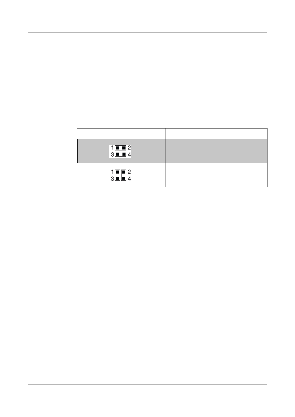
Jumper setting
Response
Underload detection
Overload detection
H
The total and partial load failure monitoring (underload) also allows
overload monitoring. For this purpose, both jumpers on the pin
strip X106 must be turned through 90°.
v Chapter 5.2 „Setting switches and jumpers“
H
The partial load setting must be made after the current limit has
been set. If the current limit setting is changed, this will also affect
the setting of the partial load fault detection.
This must be corrected accordingly, if necessary.