Appendix c: electrical connections – INFICON HPG400-SP ATM to High-Vacuum Gauge (Profibus) User Manual
Page 41
tira36e1-a (0310) BPG/HPG400 v1.cp
41
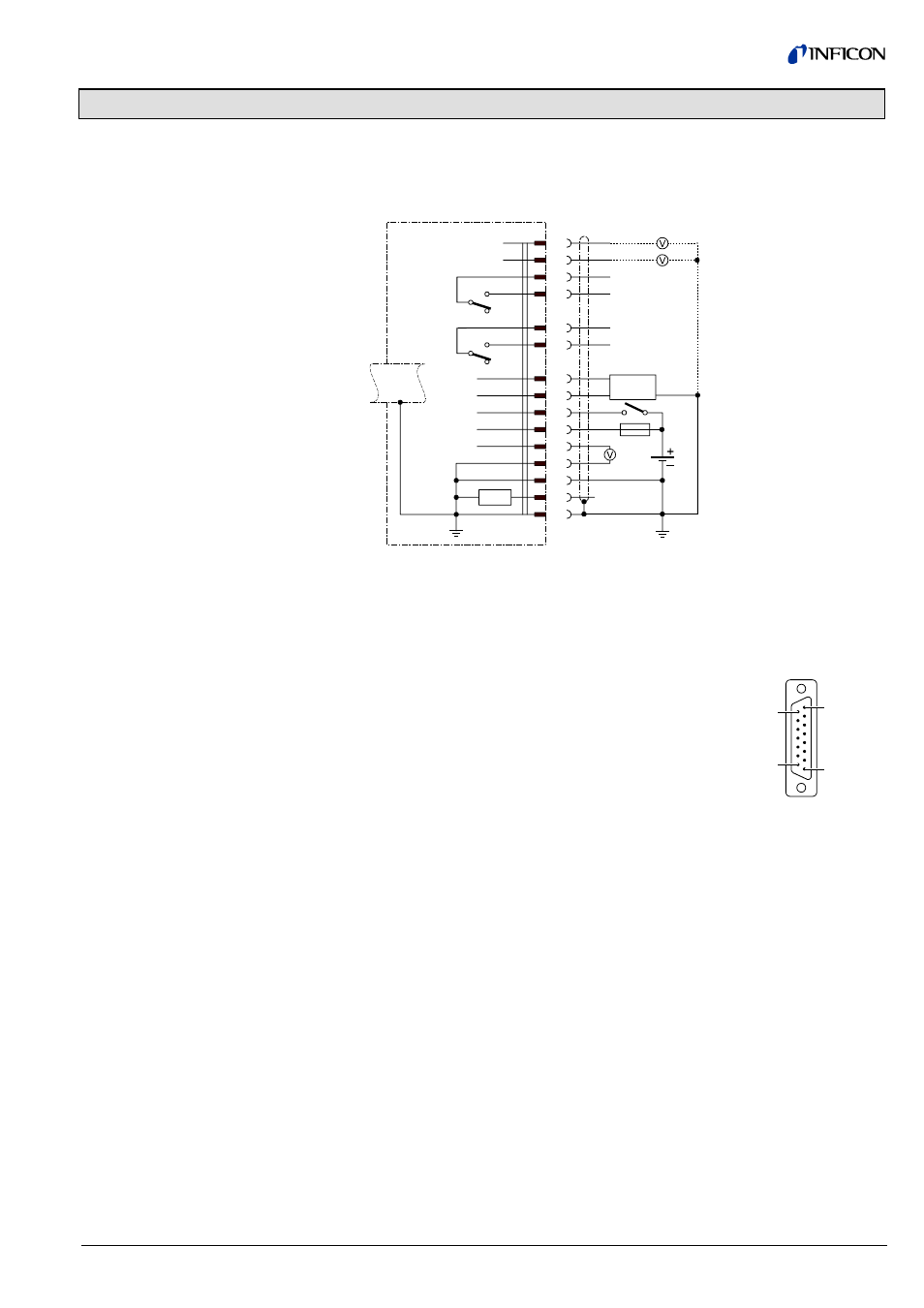
Appendix C: Electrical Connections
Technical data of gauges
→ [1],[2] [3] for BPG400-SP and [4], [5], [6] for
HPG400-SP.
Electrical connection
Pin 1 Relay Switching function A, common
Pin 2 Signal output (measuring signal)
0 … +10 V
Pin 3 Threshold value (Setpoint) A
0 … +10 V
Pin 4 Relay Switching function A, normally open contact
Pin 5 Supply common, GND
Pin 6 Threshold value (Setpoint) B
0 … +10 V
Pin 7 Degas on, active high
1)
+24
V
Pin 8 Supply of electronics unit
+24 V
Pin 9 Relay Switching function B, Common
Pin 10 Gauge identification:
BPG400-SP:
R
Id
= 42 kOhm
HPG400-SP:
R
Id
= 56 kOhm
Pin 11 Relay Switching function B, normally open contact
Pin 12 Signal common GND
Pin 13 RS232, TxD
Pin 14 RS232, RxD
Pin 15 Shielding, housing GND
BPG400-SP, HPG400-SP
TxD
RxD
Degas
1)
+U
b
R
Id
SP A
SP B
Measuring
signal
Threshold value, SP A
Threshold value, SP B
3
6
1
4
9
11
13
14
7
8
2
12
5
15
1.25 AT
24V
Degas
Identification
RS232
10
8
9
1
15
D-Sub, 15 pins
female,
soldering side
1)
Degas function only for BPG400-SP; pin 7 is not connected in the HPG400-SP.
Sensor cable connection
BPG400-SP, HPG400-SP