INFICON HPG400-SP ATM to High-Vacuum Gauge (Profibus) User Manual
Page 11
tira36e1-a (0310) BPG/HPG400 v1.cp
11
On the left of the table, the instruction signatures of the master are listed according
to their function. On the right of the table, the corresponding normal responses (AK
Normal) and error codes (AK Error) transmitted by the slave are listed.
1) The master transmits an instruction to the slave and repeats that instruction
until it receives a response from the slave.
2) The slave keeps transmitting the response to the instruction until the master
transmits a new instruction.
3) The master marks the end of the first instruction cycle by setting AK to zero.
Only after that, a new instruction/response cycle may be started.
The PWE represents the data element to be transmitted.
If a byte is to be transmitted, that byte has to be in position 8 of the parameter
channel.
Integers are transmitted with bytes 7 and 8. Double integer and float values are
transmitted with bytes 5 … 8.
In the event of a transmission error (AK response signature = 7), the slave trans-
mits an error code in byte positions 7 and 8 (data type: INT16).
Error code Meaning
0
Undefined slot
1
Parameter not changeable
2
Lower or upper value range limit overflow
3
Index error
5
Data type error
17
Instruction not allowed in this state
18
Other errors
201
Already in requested state
202
Object state conflict
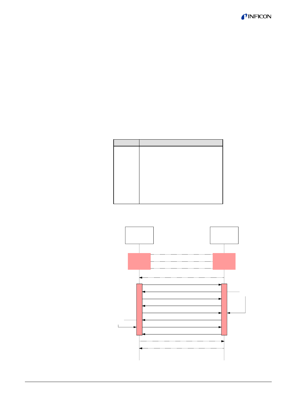
The following diagram shows an example of a data request from a master to a
BPG400-SP / HPG400-SP via parameter channel.
AK(RS) = 0
BPG400-SP
HPG400-SP
DP-Master
AK(RS) = 0
AK (IS) = 1
AK(RS) = 1
AK (IS) = 1
Parameter
Request
(Client)
AK(RS) = 0
AK (IS) = 1
AK(RS) = 0
AK (IS) = 0
AK(RS) = 0
Store
Data
AK (IS) = 0
AK(RS) = 0
Parameter
Request
(Server)
AK(IS) = 0
AK(IS) = 0
Fetch
Data
Instruction – response
sequence
2.2.1.2 PWE Parameter
Process Value
2.2.1.3 Error Code
(Error Message)