INFICON Sputtering Sensor User Manual
Page 35
2 - 13
IP
N 07
4-
15
7L
Sputtering Crystal Sensor Operating Manual
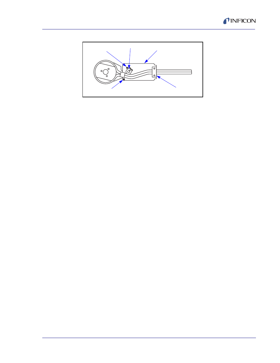
Figure 2-8 Bottom View
4
Place the sensor cover on the shutter module assembly as shown in
. The sensor water lines will fit between the shutter pivot and the stop screw.
Carefully bend the water lines as shown.
5
Position the water line clamp on the shutter assembly and install the two
mounting screws. Tighten the screws finger tight.
6
Position the sensor cover as shown in
. The shutter should cover the
sensor cover as shown. It may be necessary to align the sensor slightly to
achieve correct positioning.
7
The plane of the shutter and sensor cover should be parallel as shown in
. Again, it may be necessary to align the sensor slightly to achieve
correct positioning.
8
Tighten the two water tube clamp screws.
9
Manually rotate the shutter away from the sensor cover as shown in
and then let it go; the return operation should be smooth and unobstructed.
10
Install the actuator cover on the shutter actuator assembly and install the
actuator cover screw (4-40 x 3/16). (Refer to
11
Install the sensor body assembly into the sensor cover. The assembly will now
appear as shown in
.
Stop Screw
Shutter Pivot
Actuator
Mounting Bracket
Water Tube Clamp
Stop Screw