Zeroing the incra stop to the end of a board, Dual incra stop operations – INCRA Pro Fence System User Manual
Page 7
7
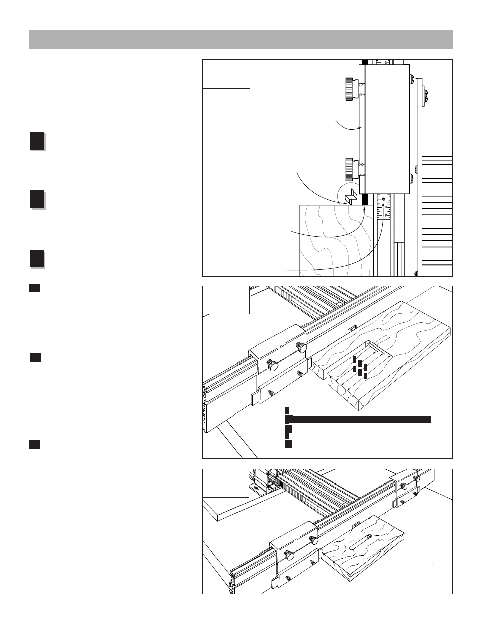
Zeroing the INCRA Stop to
the End of a Board
For most applications, you will be using your
INCRA Stop on the outfeed end of the INCRA
Fence to control the length of a cut relative to
the front end of the board. Here is how to set
the initial scale position for this type of setup:
After installing the bit you wish to use,
set the fence to bit distance at about 1".
Place a square cut piece of scrap stock
against the fence with the end of the board
against the infeed side of the bit. Turn the bit to
find the high spot.
Next, lock the INCRA Stop to the fence on
the outfeed side of the bit with the plastic
stop strip as close as possible to the end
of the board. Adjust the position of the stop
strip until both the strip and the bit contact the
end of the board. See Fig. 13.
You now have the choice of setting
the sliding scale to one of three initial
positions:
In most cases, you will simply slide the
scale to align the 0" mark on the scale
with the end of the INCRA Stop nearest the
bit. When set to this initial position, the scale
reading at any subsequent INCRA Stop location
will give you a direct readout of the total length
of the cut. (See Dimension “A”, Fig. 14.)
If you wish the subsequent scale readings
to reflect the distance from the front end of
the board to the center of the cut (Dimension
“B”, Fig. 14), slide the scale to an initial reading
under the end of the INCRA Stop equal to
minus one half of the bit diameter. Example:
If you are using a
1
⁄
2
" diameter bit, complete
Steps 1 and 2 above then slide the scale to
read negative
1
⁄
4
".
If you want the scale reading for future
INCRA Stop locations to reflect the
distance between the end of the board and the
outfeed edge of the cutter (Dimension “C”, Fig.
14), then slide the scale to an initial reading
equal to minus the bit diameter.
Dual INCRA Stop
Operations
Using the same setup process described above
and a second INCRA Stop, you will find the
precise positioning of mortises on a board quite
simple. The INCRA Jig Projects and Techniques
book covers this technique fully and includes
several unique projects which feature dual
INCRA Stop operations.
1
2
3
A
B
C
Fig. 13
Top view of
stop setup
First:
Slide the board
up to contact
the “high spot”
on the bit
Second:
Lock the INCRA Stop to the
fence and adjust the position
of the plastic stop strip to
contact the end of the board
Third:
Slide the scale to read one of
the initial scale settings as
described in Fig. 14 below
INCRA
Stop
Fig. 14
Initial scale
setting
Slide scale to 0" for a direct readout of Dimension “A”
Slide scale to “minus
1
/
2
of the bit diameter” for a direct
readout of Dimension “B”
Slide scale to “minus diameter of the bit” for a direct
readout of Dimension “C”
A
‑C
.
A
B
.
Fig. 15
Dual stop
operations
A
A
A
B
A
C
A
‑A
.