HYDAC HLB 1300 User Manual
Page 24
User Manual HYDACLab
®
23.10.2008
9
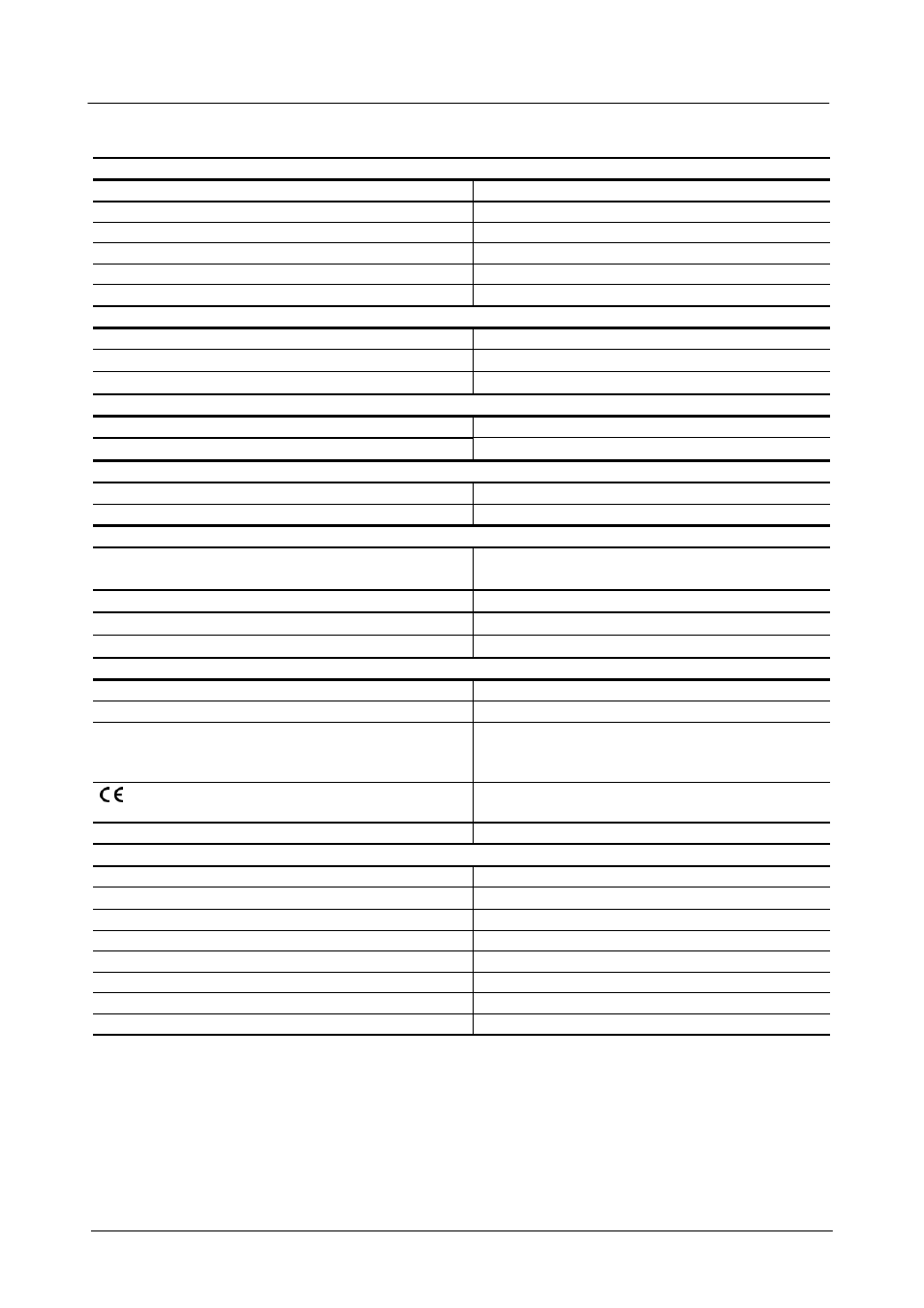
8. Technical specifications
Input data
Relative humidity
0 .. 100 % saturation
Temperature
-25 ..
+100 °C
Dielectric constant (ε
R
)
1 ..10
Operating pressure
< 50 bar
Pressure resistance
< 600 bar
Fluid flow velocity
< 5 m/s
Output data - Humidity measurement
Output signal
4 .. 20 mA
(corresponds to 0 .. 100 %)
Calibration accuracy
≤ ± 2 % FS max.
Accuracy
≤ ± 3 % FS typ. *
Output data - Temperature measurement
Output signal
4 .. 20 mA
(corresponds to -25 .. +100 °C)
Accuracy
≤ ± 3 % FS max.
Output data - Relative change in dielectric constant (ε
R
)
Output signal
12 mA ± 8 mA
(± 30 % of IV)
Accuracy
see below **
Switching output
Signal 1 (N/C)
PNP transistor switching output 0.5 A max.
switching level
≥ U
B
– 4 V
Preset warning level SP1 relative humidity
≥ 85 %
Present warning level SP1 temperature
≥ 80 °C
Present warning level SP1 dielectric constant
± 15 %
(temperature compensated)
Ambient conditions
Nominal temperature range
+20 .. +80 °C
Storage temperature
-40 .. +90 °C
Fluid compatibility
Mineral oils HLP (HLP-D on request)
Esters: HEES, HETG
Seals: FPM
mark
EN 61000-6-1, EN 61000-6-2
EN 61000-6-3, EN 61000-6-4
Protection class to DIN 40050
IP 67
Other data
Supply voltage U
B
10 .. 36 V DC
Supply voltage residual ripple
≤ 5 %
Mechanical connection
G ¾ DIN 3852 E
Torque value
30 Nm
Electrical connection
M12x1, 5 pole
Reverse polarity, short circuit protection
Provided
Housing Stainless
steel
Weight approx.
205
g
FS (Full Scale); refers to full dynamic range IV (Initial Value)
* The best accuracy achievable when measuring relative humidity is heavily dependent on the type of fluid or fluid
additive(s) involved. More precise information on this is available on request.
** The measurement accuracy of relative change in dielectric constant
varies according to the application, the types of fluids involved and the sensor's own calibration.
More detailed information on this is available on request.