Festo FLSR User Manual
Page 23
FLSM/FLSR
Festo FLSM/FLSR 1209d English
23
Attachment of moveable masses
Definition
Moveable mass = working load + mass of the lever used
Caution
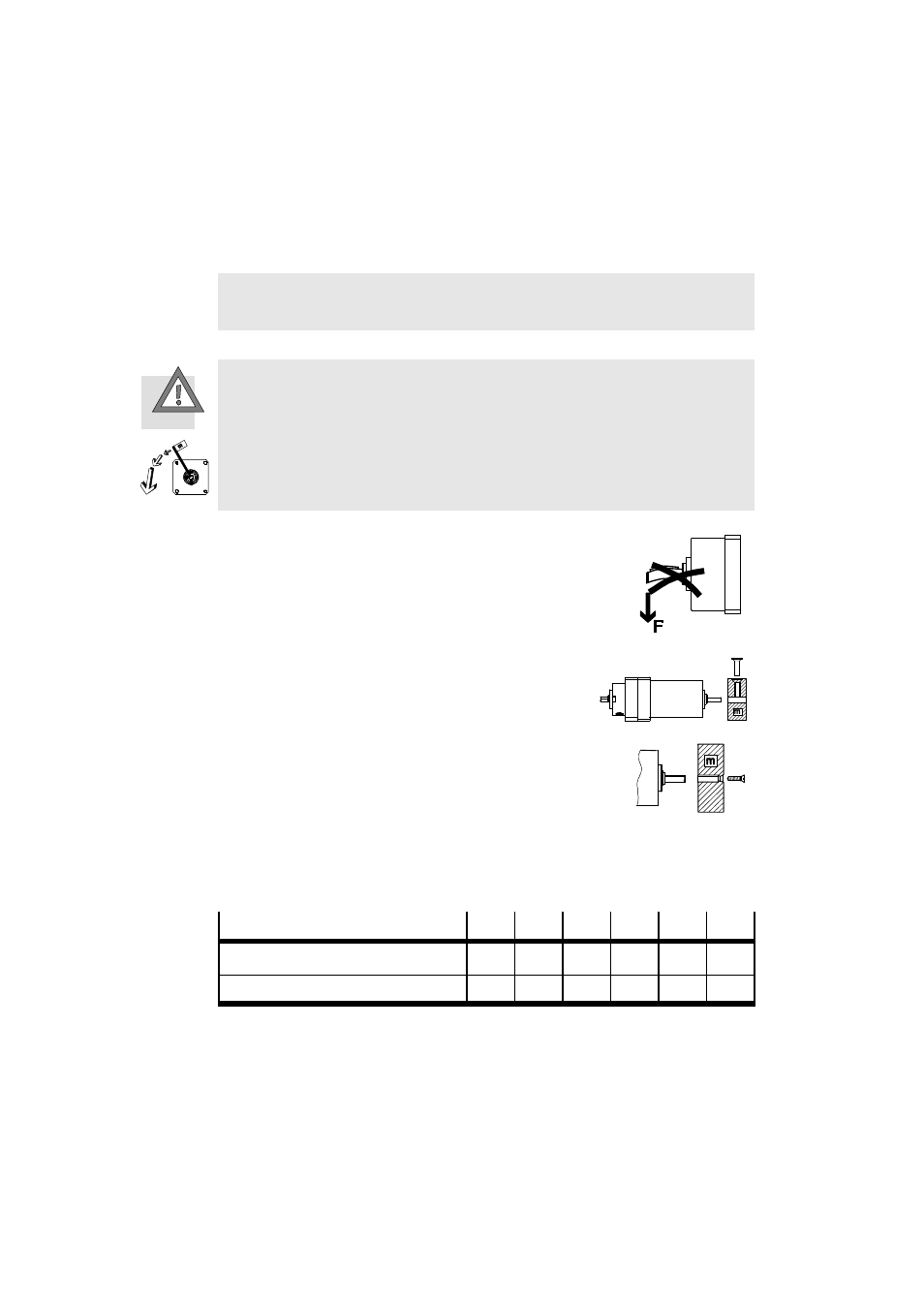
There is no overrun block available in the direction of rotation. When the top
dead centre is passed, the mass is also accelerated by its gravitational force.
S Make sure that the moveable mass does not crash downward when it passes
top dead centre. Use external locking devices, such as timed cylinders, to
prevent puncturing.
When placing the moveable masses, always
observe the following:
S Install the free-wheel without tilt.
S The permissible axial and radial forces
must not be exceeded (chapter 13).
Make sure that the moveable mass cannot
slide off the output-drive shaft. Design
variants:
S Free-wheel with flattened output-drive
shaft without key in accordance with
Fig. 13 (FLSM-6/8).
S Free-wheel with thread on the face of the
output-drive shaft in accordance with
Fig. 14 (from size 10).
Fastening of the moveable mass to the face of the output-drive shaft
FLSM/FLSR
10
12
16
25
32
40
Connecting thread, face
M2.5
M3
M3
M4
M5
M6
Tightening torque [Nm]
0.76
1.2
1.2
2.9
5.9
9.9
Fig. 12
Fig. 13
Fig. 14