ERICO EPD100HZ120TDF (100Hz, 120 VAC) Fused Primary Surge Protectors User Manual
Installation instructions, Fused primary surge protectors, Parallel tvss filters
Fused Primary Surge Protectors
Parallel TVSS Filters
1998 ERICO
Inc, 34600 Solon Rd, Solon, OH 44139
Page 1 of 3
Doc: HBCR1231DOC.DOC, Iss: 2, Date: 27JUL98
EPD25HZ120TDF (25Hz, 120 VAC)
EPD100HZ120TDF (100Hz, 120 VAC)
Installation Instructions
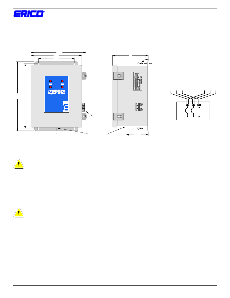
FORM C
CONTACTS
CABLE ENTRY
COM
NC
NO
MOUNTING SCREWS
SUPPLIED
6
6
FIG. 1
FIG. 2
FIG. 3
10 3/4
11 1/2
8 1/2
9 1/4
3 3/4
UNIT OPERATING S TATUS
120 VAC - 100 HZ
PANEL PROTECTOR
STAGE 1
STAGE 1
STAGE 2
STAGE 2
FORM 'C'
CONTACTS
NC
COM
NO
LINE 1
LINE 2
E R I C O
P R O T E C T I O N
D E V I C E S
R
TM
INPUT
OUTPUT
EPD
L1
L1
L1
L2
L2
L2
G
G
G
1
2
3
4
PREPARATION
DANGER: Electrical shock or burn hazard.
Installation of Primary Surge Protector should be
made by qualified personnel. Failure to lockout
electrical power during installation or maintenance can
result in fatal electrocution or severe burns.
1. Disconnect and lockout power to the breaker box (load
center) or point where the Primary Surge Protector is to
be installed. Follow all applicable electrical codes &
procedures.
CAUTION: Check to make sure line voltage does
not exceed Surge Protector voltage requirement.
Note also the AC frequency requirements of these
Surge Protectors.
PROTECTOR MOUNTING AND LOCATION
2. The Surge Protector is to be mounted as close to the
power entrance point as possible to maximize
performance.
3. The Surge Protector can be attached directly to a wall
panel:
a) Drill 3/16 diameter pilot hole in the wall panel. See
FIG. 1 for mounting hole configuration.
b) Mount unit with (4) #12 x 3/4-lg. screws supplied.
See FIG. 2
AC ELECTRICAL CONNECTION
4. The Surge Protector should be wired as shown in FIG. 3
to provide maximum performance. This allows for a
“zero” lead length or Kelvin connection to the Surge
Protector. When using this recommended method, use
the two outer knockouts, so that the input wiring enters
on one side, and the output wiring exits on the other side.
It is possible to wire the unit parallel to the supply. In
this case, tap conductors are run into the unit (the single
center knockout may be used), and only one wire lead
terminates on each wiring terminal. This method does
not provide the optimum surge performance of the
recommended Kelvin connection method.
NOTE: Where a supply transformer is used, the Surge
Protector should be placed on the load side of the supply
transformer for optimal performance.
5. The knockouts are sized to fit 1” fittings, but may be
enlarged if necessary to take larger fittings. The
terminals will accept wiring up to #2 AWG, but the
maximum wire size possible will be determined by the
type of wire and the fitting size used. Ensure that the
wiring size chosen meets applicable codes.
NOTE: The Surge Protector must be properly and securely
connected to the system ground. Note also that there is no
neutral connection available on this unit.