Tdx modular diagnostic sheet – ERICO TDX Modular User Manual
Page 2
DANGER
ELECTRICAL SHOCK OR BURN HAZARD. HAZARDOUS VOLTAGES EXIST INTERNAL TO THE TDX. THIS UNIT SHOULD BE INSTALLED AND SERVICED ONLY BY QUALIFIED PERSONNEL IN
CONFORMANCE WITH ALL GOVERNING CODES AND INSTRUCTIONS. FAILURE TO LOCKOUT ELECTRICAL POWER DURING INSTALLATION OR MAINTENANCE CAN RESULT IN FATAL
ELECTROCUTION, SEVERE BURNS, OR OTHER INJURIES. BEFORE WORKING WITH OR MAKING ANY CONNECTIONS TO THIS DEVICE, BE SURE THAT POWER HAS BEEN REMOVED FROM
ALL ASSOCIATED WIRING, ELECTRICAL PANELS, AND OTHER ELECTRICAL EQUIPMENT.
1. The power supply to the TDX should always be turned (and locked) OFF before the unit is accessed for any reason.
2. Prior to installation, ensure that the TDX is of the correct voltage, current, phasing, and frequency for the applicable rating of the power distribution system.
3. Diagrams are for reference only. Schematics are representative of typical applications and are only to be used for reference.
WARNING
1. ERICO products shall be installed and used only as indicated in ERICO product instruction sheets and training materials. Instruction sheets are available at www.erico.com and from
your ERICO customer service representative.
2. ERICO products must never be used for a purpose other than the purpose for which they were designed or in a manner that exceeds specifi ed load ratings.
3. All instructions must be completely followed to ensure proper and safe installation and performance.
4. Improper installation, misuse, misapplication or other failure to completely follow ERICO instructions and warnings may cause product malfunction, property damage, serious
bodily injury and death.
SAFETY INSTRUCTIONS
All governing codes and regulations and those required by the job site must be observed. Always use appropriate safety equipment such as eye protection, hard hat, and gloves as
appropriate to the application.
WARNING
ERICO products shall be installed and used only as indicated in ERICO’s product instruction sheets and training materials. Instruction sheets are available at www.erico.com and from
your ERICO customer service representative. Improper installation, misuse, misapplication or other failure to completely follow ERICO’s instructions and warnings may cause product
malfunction, property damage, serious bodily injury and death.
Copyright ©2014 ERICO International Corporation. All rights reserved.
CADDY, CADWELD, CRITEC, ERICO, ERIFLEX, ERITECH, and LENTON are registered trademarks of ERICO International Corporation.
www.erico.com
IP8289_A E158IS14NAEN WB0414
TDX Modular Diagnostic Sheet
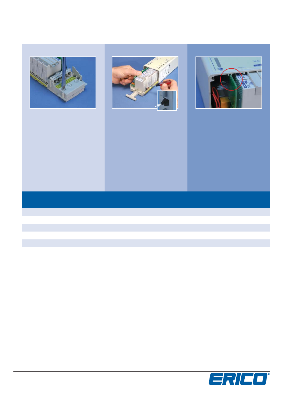
Make sure the green PCB
board lines up with the slots
as you slide the tray into the
housing. Push tray fi rmly in
to housing and replace base
plate and screws. For models
with a surge counter, the slot
will start 1”(25.4mm) into
the housing.
Replacement modules can be
identifi ed by the chart below
or by the plastic strip on
the side of the tray. A small
fl athead screw driver (above
photo) will assist in removing
the tripped module. Modules
ship with a black key for
use in dinrail bases. This key
must be removed prior to
installation into the TDX tray.
Remove the fuse by turning
the fuse ejector 90 degrees
using a 3/16” fl at head screw
driver (recommended.)
Make sure the head of the
screw driver is as large as the
access point to prevent
stripping the slot.
Orderable replacement
part number
Part number
on module
Number on tray
Model Voltage
TDS150M150
TDS150 1S(R)-150
TDS 150
120/208, 120/240, 120/240D
TDS150M240
TDS150 1S(R)-240
TDS 240
240D, 120/240D
TDS150M277
TDS150 1S(R)-277
TDS 277
277/480, 277/480TT
TDS150M560
TDS150 1S(R)-560
TDS 560
347/600, 480D
SGD125M
SGD125 1S(R)NE
SGD 125
277/480TT (N-E)
Reinstalling the Tray
Replacing modules
Replacing fuses
For any other issues, visit erico.com for a list of technical support contact numbers.
Remove with pliers