Installation after the main disconnect, Installation before the main disconnect – ERICO CRITEC SES65 240 AC Panel Protector User Manual
Page 3
3
Phone: 800-248-9353
www.erico.com
INDOOR/OUTDOOR INSTALLATION & OPERATING INSTRUCTIONS
SES65 120/240 AC Panel Protector
HOT
NEUTRAL
HOT
GROUND
BLACK
GREEN
BUILDING
GROUND
120V
240V
120V
USE BUS TO CONNECT GROUND
WIRES FOR TELCO OR COAX LINES
METER
30 A BREAKER OR
SUB-FEED LUG SET
B
B
B
MAIN
DISCONNECT
FROM SES65 120/240
GROUND BUS
30 A BREAKER
OR SUB-FEED
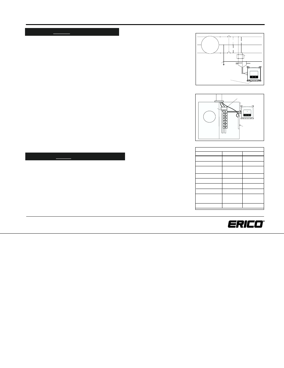
Figure 2
Figure 3
Installation BEFORE The Main Disconnect
WARNING: REMOVE THE METER OR OTHERWISE DISCONNECT THE AC POWER BEFORE
BEGINNING THE INSTALLATION!!!
The SES65 120/240 should be installed by qualified and authorized personnel.
USE A TEST LAMP TO CONFIRM THAT THE POWER HAS BEEN REMOVED!!
The SES65 120/240 protector is UL Listed for installation either before or behind the main
service disconnect. The mechanical installation to the meter pan or meter side of the serv-
ice panel is as described in figures 1- 3, as close as possible to the wiring between the
meter and the service disconnect.
SES65 120/240 CONNECTIONS:
1. The SES65 120/240 wires should be connected to the points "B" in figure 4. The
connections can be made at the meter socket or on the wiring to the main disconnect.
2. Connect the green (ground) wire to the service raceway, the ground bus, or any other
part of the grounding electrode system. The ground wire should be kept as short as
possible.
3. Connect the 2 black wires to the two phase terminals of the meter socket or to the
conductors to the disconnect. An insulated tap connector such as ILSCO KUPLER IPC 4/0-#6
is a fast and easy way to connect the black (phase) wires to the service conductors.
4. Check the connections!
5. Replace the meter, or turn the AC power switch back on.The two green lights on the
unit should come on, confirming that the connections are correct and there is power
to both phases.
Installation AFTER The Main Disconnect
1. The SES65 120/240 should be installed by a qualified electrician.
2. Turn "OFF" and lock out the power to the enclosure in which the unit is to be installed.
3. Connect the green wire to the ground bus or connector.
4. Install the appropriate 2 pole, 30 ampere circuit breaker or lug kit (See table) to the
panelboard or meter combination device. If a sub-feed lug kit is available, it is a better
and more economical connection than a breaker.
5. Connect the black leads to the load terminals of the circuit breaker or lug kit and tighten
to the required torque.
6. Double check connections, then reconnect power.
7. When both LEDs are on, the protector is functioning as desired.
WIRING SCHEMATIC
RECOMMENDED BRANCH CIRCUIT BREAKER
SIEMENS / GOULD / ITE
ITE PUSHMATIC
MURRAY / CROUSE-HINDS
SEARS
GE
SQUARE D QO
SQUARE D HOMELINE
CUTLER-HAMMER CH
CUTLER HAMMER BR
CHALLENGER
SYLVANIA / WESTINGHOUSE
THOMAS & BETTS / BRYANT
SIEMENS
SIEMENS
MURRAY
GE
SQUARE D
SQUARE D
CUTLER-HAMMER
CUTLER HAMMER
THOMAS & BETTS
Q230
P230
MP230
THQL2130
QO230
HOM230
CH230
BR230
TB230
If your panel is: Manufacturer Catalog Number