Installation instructions, Dinline alarm relay – ERICO DAR 275V User Manual
Page 2
DINLINE ALARM RELAY
INSTALLATION INSTRUCTIONS
www.erico.com
Page 2 of 2
Doc: HBCR1681, Rev: 1
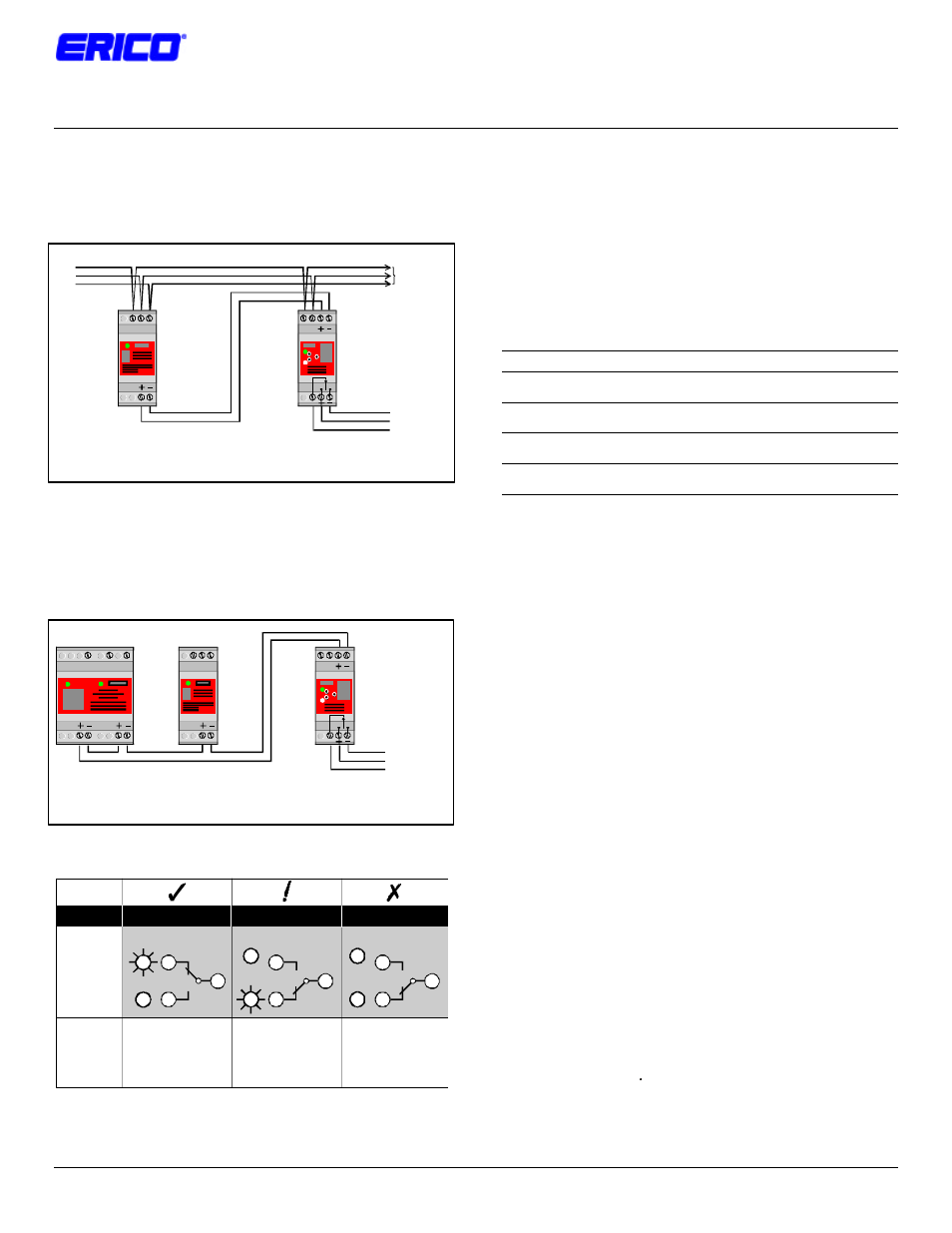
5. INTERCONNECTION
When connecting the DAR to a single opto-coupler output the
+ terminal of the SPD should connect to the + terminal on the
DAR. The – terminal should connect to the -- terminal.
To transient
protected
equipment
To remote alarm circuit
DSD 2S/2T
N E
Ph
DAR
N
Ph
Voltage free contacts
Opto-coupler output
+/- terminal connections are polarity sensitive. Do not reverse.
When connecting the DAR to multiple opto-couplers the opto-
couplers should be connected in series with + terminal of one
connected to the – terminal of the next. The DAR + terminal
should connect to + SPD terminal at one end of the series
connection and the – DAR terminal connect to the – SPD
terminal at the other end of the series connection.
DSD 2S/2T
Up to 16 connections per DAR module
N
E
Ph
N E
Ph
DAR
N
Ph
Voltage free contacts
+/- terminal connections are polarity sensitive. Do not reverse.
5. STATUS INDICATION
Normal (green) indicator OFF
Red indicator ON
Relay is de-energised
Power is supplied
Normal (green) indicatorOFF
Red indicator OFF
Relay is de-energised
Power is OFF
Normal
4
Fault
6
8
Normal
4
Fault
6
8
DSD in alarm mode or power
to DSD has been removed
Power to DAR removed
Protection status unknown
DISPLAY
EXPLANATION
Normal
Fault
6
4
8
Normal (green) indicator ON
Red indicator OFF
Relay is energised
Power is supplied
Normal operation
Protection Operational
STATUS
Protection Alarm
Fault Mode
6. FUSING AND ISOLATION
Overcurrent protection must be installed in the upstream circuit
of the power supply to the DAR to provide protection to the
unit itself and the wiring in case of fault conditions.
The fuse rating should be based on the wiring size used to
connect to the DAR Ph & N terminals. Australian regulations
AS3000-1991, Table B2 specifies the following upstream
protection for single phase circuits, unenclosed in air.
Cable Size
HRC Fuse or
CB Rewirable Fuse
1.5mm
2
16A
12A
2.5mm
2
20A
16A
4mm
2
25A
20A
6mm
2
32A
25A
Where overcurrent protection of the appropriate rating or
smaller is already fitted in the upstream circuit, overcurrent
protection at the DAR will not be required
6. MAINTENANCE & TESTING
Before removing a DAR unit from service, ensure that the
power has been removed. Maintenance, testing and
replacement should only be undertaken by qualified personnel.
Testing of a DAR unit which is connected to a fully functional
DSD unit can be accomplished by removing power to the DSD
only. The DAR Status indication and output contacts should
alter from the Normal to Fault condition.
Testing of the DAR unit alone may be accomplished by
disconnecting the + / -connections to the unit. When power is
applied the DAR “Fault” Status Indicator should be illuminated.
By connecting the + / - terminals together, the “Normal” Status
Indicator should be illuminated. The output contacts should
alter to the appropriate state.
7. USE OF OTHER INTERFACES
Only DAR units are recommended for the interfacing of
equipment to the DSD, TDS & TDF opto-coupler alarm output
circuit(s). The direct connection of other equipment to these
opto-coupler alarm outputs may not provide sufficient isolation
or exceed the opto-coupler specifications. This may damage
the SPD and/or the connected equipment. Warranty may be
voided under such circumstances.
NOTE: In connecting to the SPD opto-coupler alarm
output(s), do not reverse the +/- connections as
damage may occur
L
N
E
( 4 - 6 m m )
B u n d l e / t w i s t
t o g e t h e r
S
u
p
p
l
y
K
e
e
p
a
s
s
h
o
r
t
a s p r a c t i c a l
S e e s e c t i o n 8
f o r f u s i n g d e t a i l s
N
L