Cadweld, Rail grounding connections – web bonds – ERICO CADWELD Rail Grounding Connections – Web Bonds User Manual
Page 2
!
!
!
!
CADWELD
®
Rail Grounding Connections – Web Bonds
Refer to the mold tag for applicable instruction sheets.
IPRGW_B
IPRGW_B R1073S10WWEN PUR0312
WARNING:
The area of the rail where the web bond will be applied
and the bond terminals must be clean and dry. Failure to comply
can cause poor bonding, excessive weld porosity, and/or spewing molten
welding material with the potential for serious burns to the worker.
2. Use abrasive cloth or wire brush on the bond terminals if needed to
remove surface oxidation.
CAUTION:
The bond terminals must have a bright surface. Failure to
comply with this may result in a less than optimal weld. See Figure 4.
!
!
!
FIGURE 4
WARNING:
The area of the rail web to
be bonded must be lightly ground to a
bright fi nish with no visible scratch marks
or gouges (normal uniform fi nishing marks
are acceptable). Failure to observe this may
result in visible scratches or gouges due to overly
aggressive grinding that are potential crack
initiators and that may lead to rail breaks causing
derailment accidents with property damage,
injury and death to others. See Figure 5.
3. Lightly grind the rail surface using an ERICO approved grinding wheel
that is self-cleaning or a CADWELD
®
brand Rail Head and Web Cleaner
(Part SBB394C). Grinding wheels with resin binders tend to leave a
surface
fi lm that may contaminate the surface, interfering with the
achievement of an optimum bond and causing weld porosity.
FIGURE 5
FIGURE 6
CAUTION:
Grinding must not be done more than 4 hours prior
to bonding. If the time lapse is longer, suffi cient contaminating rust may
re-form requiring additional grinding. Failure to observe this may result in
a less than optimum bond.
4. Dry the mold and rail by heating them to about 250°F (120°C) with
a small propane torch.
WARNING:
The rail and mold must both be warmed to drive off
moisture. Failure to observe this may result in weld spatter with the
potential for serious burn injury, and a less than optimum bond with
excessive porosity. See Figure 6.
!
!
!
!
WARNING:
Rebonding over the application of an earlier web bond
is strictly forbidden! Rebonds must be applied at least two inches away
(centerline to centerline) from an earlier bond to avoid serious structural
harm to the rail. Failure to observe this may result in a rail break leading to
property damage, injury or death to others.
WARNING:
Back-to-back bonding of web bonds is strictly forbidden!
Bonds made on the opposite side of the rail to an earlier web bond must be
applied at least two inches away (centerline to centerline) from the earlier
bond to avoid serious structural harm to the rail. Failure to observe this may
result in a rail break leading to property damage, injury or death to others.
FIGURE 7
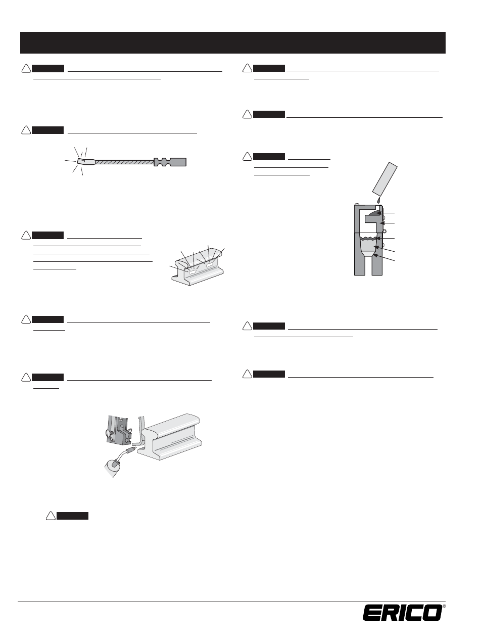
CAUTION:
Install only the
specifi ed welding material
in the mold crucible. Use only
the welding material size that
is specifi ed on the mold. ERICO
brand of welding material (F80) is
formulated specifi cally for use with
rail steels; it is packaged in a blue
tube with a yellow cap. Dump all
of the welding material into the
crucible, then carefully tap the tube
on a hard surface to loosen the
starting material from the bottom
of the tube and distribute half
on top of the welding material,
close the mold cover, and pour the
remainder in the opening of the
mold cover. See Figure 7. Failure
to comply may result in diffi culty
getting the reaction started and/or
an unacceptable weld.
CAUTION:
Avoid direct eye contact with the “fl ash” of light from
the ignition of the starting material.
5. Position yourself upwind of the mold, on the fi eld side of the rail.
Place the tip of the fl int igniter at the cover opening and ignite.
Remove the igniter quickly to prevent fouling.
CAUTION:
Allow 15 seconds for mold cooling after the reaction.
This will permit the molten metal to solidify. Then carefully disengage the
welder device and pull the mold straight back from the rail. Failure to
observe this may result in mold damage and its premature scrapping.
Molds can generally be re-used up to 50 times.
6. Carefully open the mold cover and break up the slag in the crucible
using the blade of the mold cleaning tool. Dump the slag from the
crucible and remove slag from the taphole using the curved end of
the mold cleaner. Dump slag in the ballast, not onto the ties.
7. Check the molds for breakage or residual slag before proceeding
with the next weld.
Note: If you have any questions or require further instructions, or would
like training, contact ERICO at 1-800-447-7245.
WARNING:
1. Connections should not be made to load bearing rail steel other than at the neutral axis of the rail or at the head of the rail within
the
confi nes of the joint/splice bar.
2. All connections to rail steel should only be made where the rails are fully supported, or to rail that is non-load bearing in its use.
3. The welding material size for the connection to rail steel should not be greater than 250 grams (which, in general, corresponds
to a maximum cable size of 500 kcmil (240 mm
2
).
Disk
Welding Material
1/2 Starting Material
Crucible Cover
1/2 Starting Material
Copyright ©2010, 2012 ERICO International Corporation. All rights reserved.
CADDY, CADWELD, CRITEC, ERICO, ERIFLEX, ERITECH, and LENTON are registered trademarks of ERICO International Corporation.
www.erico.com
2