Cadweld, Propulsion rail - joint bond – ERICO CADWELD Propulsion Rail - Joint Bond User Manual
Page 4
!
!
!
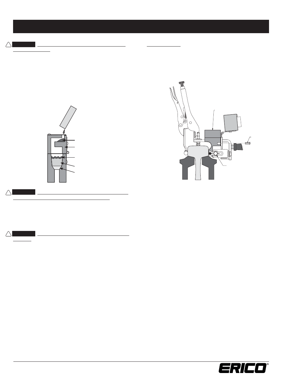
CAUTION:
Use only the specifi ed welding material in
the mold crucible. Use only the welding material size that is
specifi ed on the mold. ERICO brand of welding material (F80)
is formulated specifi cally for use with rail steel; it is packaged in
a blue tube with a yellow cap. Dump all of the welding material
into the crucible, then carefully tap the tube on a hard surface
to loosen the starting material from the bottom of the tube and
distribute half on top of the welding material, close the mold
cover, and pour the remainder in the opening of the mold cover.
See Figure 12. Failure to comply may result in diffi culty getting
the reaction started and/or an unacceptable weld.
Changing Molds (See Figure 13.)
A. Remove mold back frame Screw “A”.
B. Pull out worn mold.
C. Insert new mold, replace Screw “A”. Check bolt “B” to
be sure it is not too tight. Mold must be free to move within
frame against pressure spring.
FIGURE 12
www.erico.com
Copyright ©2010, 2012, 2013 ERICO International Corporation. All rights reserved.
CADDY, CADWELD, CRITEC, ERICO, ERIFLEX, ERITECH, and LENTON are registered trademarks of ERICO International Corporation.
FIGURE 13
4
IPRPC_C R681IS09WWEN PUR1113
CADWELD
®
Propulsion Rail - Joint Bond
Refer to the mold tag for applicable instruction sheets.
IPRPC_C
V. DOUBLE BONDING PROCEDURE
1. Place fi rst bond in welder and locate edge of right hand mold
approximately 2” from right edge of joint.
NOTE: Placement of fi rst bond as low as possible on rail head
will facilitate positioning of second bond. See Figure 2.
2. Follow Section IV WELDING PROCEDURE for adjusting,
clamping and welding.
3. Upon completion of welding fi rst bond, tap cable, at center
of bond, down with hammer against splice bar for suffi cient
clearance for welding second bond.
4. With second bond installed in welder, center left hand mold
between
fi rst bond connections and clamp welder to rail.
Check that mold face fi ts tight against rail, as low as possible.
5. Follow Section IV WELDING PROCEDURE.
Note: If you have any questions or require further instructions,
or would like training, contact ERICO at 1-800-447-7245.
CAUTION:
Avoid direct eye contact with the “fl ash” of
light from the ignition of the starting material.
6. Position yourself upwind of the molds, place the tip of the
fl int ignitor at the cover opening and ignite. Remove the
igniter quickly to prevent fouling If igniting two molds in
sequence, ignite the downwind mold fi rst.
CAUTION:
Allow 15 seconds for mold cooling after the
reaction. This will permit the molten metal to solidify.
7. Carefully open the mold cover and break up the slag in the
crucible using the blade of the mold cleaning tool.
8. Unlock clamp and remove welder by pulling the mold straight
back from the rail. Failure to observe this may result in mold
damage and its premature scrapping. Molds can generally be
re-used up to 50 times.
9. Dump the slag from the crucible and remove the slag from
the taphole using the curved end of the mold cleaner. Dump
slag in the ballast, not onto the ties.
10. Check the molds for breakage or residual slag before
proceeding with the next weld.
Disk
Welding Material
1/2 Starting Material
Crucible Cover
1/2 Starting Material
Screw “A”
Bolt “B”
Pull Out Worn Mold