Cadweld, Rail joint head bonds, Tap hole bond clip terminal bond – ERICO CADWELD Rail Joint Head Bonds User Manual
Page 3
www.erico.com
3
!
!
IV. WELDING PROCEDURE
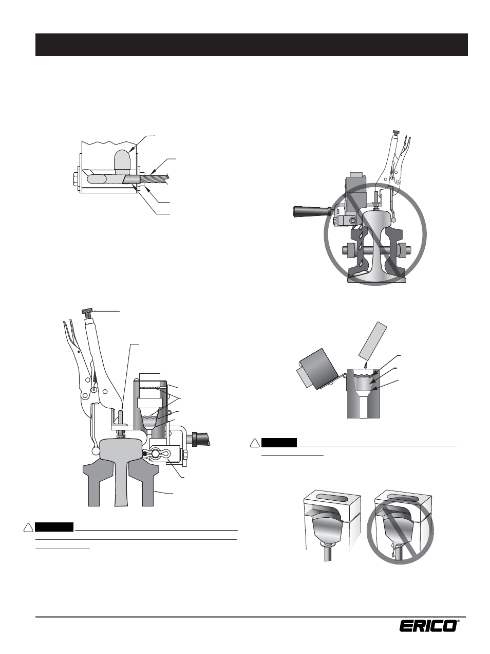
1. Place bond in welder with fl at surface against rail head and
end of terminal against bond clip. This correctly positions bond
in weld cavity. Be sure the bond clip is in good condition and
properly positions terminal under center of tap hole as shown.
See Figure 7.
2. Position the welder with attached molds on the rail head.
The bottom edge of the mold should be aligned with the lower
edge of the rail head. Use the mold height adjusting screws to
properly align the mold. See Figure 8.
3. Close clamp to lock welder on rail. Clamp is adjustable for rail
sizes. Check that mold face fi ts against rail and bond terminal is
held against rail by clevis. See Figure 8.
WARNING:
Correctly positioning the mold against the rail
with the welder device is critical for safety and success in
making a bond. There must be no cracks between the lower
part of the mold that contains the weld cavity and the rail
surface; if a crack is present, the mold should be discarded and
a new one used. See Figure 9. (Molds can generally be used for
up to 50 welds.) The exothermic reaction reaches a temperature
in excess of 4000°F, therefore great care must be exercised
to avoid spillage of the molten metal. Failure to observe this
warning may result in molten metal leakage onto the rail
with immediate risk of personal injury, and potentially serious
structural damage to the rail that could result in a rail break
leading to property damage, injury or death to others.
4. Insert one steel disk, dished (concave) side up, in the crucible
to cover the taphole. See Figure 10.
CAUTION:
The steel disc must be correctly installed into
the mold crucible. Failure to properly position it may result
in premature leakage into the mold area, resulting in an
unacceptable weld. See Figure 11.
5. Dump the contents of the welding material container into the
crucible, being careful not to upset the disk.
Starting Material
Welding Material
Disk
FIGURE
10
FIGURE
11
TAP HOLE
BOND CLIP
TERMINAL
BOND
Tap Hole
Bond
Terminal
Bond Clip
CLAMP ADJUSTMENT SCREW
MOLD HEIGHT ADJUSTING SCREW
SPLICE BAR
BOND CLIP
DISK
WELDING MATERIAL
STARTING MATERIA
GRAPHITE COVER
Welding Material
Starting Material
Bond Clip
Disk
Graphite Cover
Mold Height Adjusting Screw
Clamp Adjustment Screw
Splice Bar
FIGURE
7
FIGURE
8
FIGURE
9
CADWELD
®
Rail Joint Head Bonds
Refer to the mold tag for additional instruction sheet needed.
IPR_G