Enerpac SU7-Series User Manual
Page 9
9
Clearance problems are most common when using the
CAS series standard length arm, with the final clamping
position located at the side of the cylinder. You may
need to use the longer CAL Series clamp arm for these
applications. You can cut CAL series arms to meet your
own requirements, or make your own custom arms, in
accordance with the dimensions shown in Section 10.0
of this manual.
7.0 OPERATION
Swing cylinders rotate 90° during the first portion of
the stroke, continuing without rotation for the final
clamping stroke. The straight downward stroke is the
clamping stroke of the cylinder. Clamping force must
be applied only during the vertical travel, not during
the swing motion.
CAUTION: If clamping force is applied
during the rotation portion of the stroke,
internal plunger damage may result.
• To ensure maximum cylinder performance and
safety, be sure all hydraulic connections, hoses,
and fittings are properly sealed and fully tightened.
• Be sure all items are rated to withstand system
pressures. Under-rated components will not
withstand higher pressure. Using under-rated
components will lead to equipment damage and
possible personal injury.
7.1 Pressure and Flow Rate
The clamp arm length determines the swing cylinder’s
required operating pressure and flow rate.
Set operating pressure and flow rate according to the
recommendations contained in Section 3.1 for your
swing cylinder model.
IMPORTANT: Do not exceed the load-to-length
pressure ratios described in Section 3.1, tables 4
through 9. As the arm length increases, the clamping
force and maximum operating pressure are reduced.
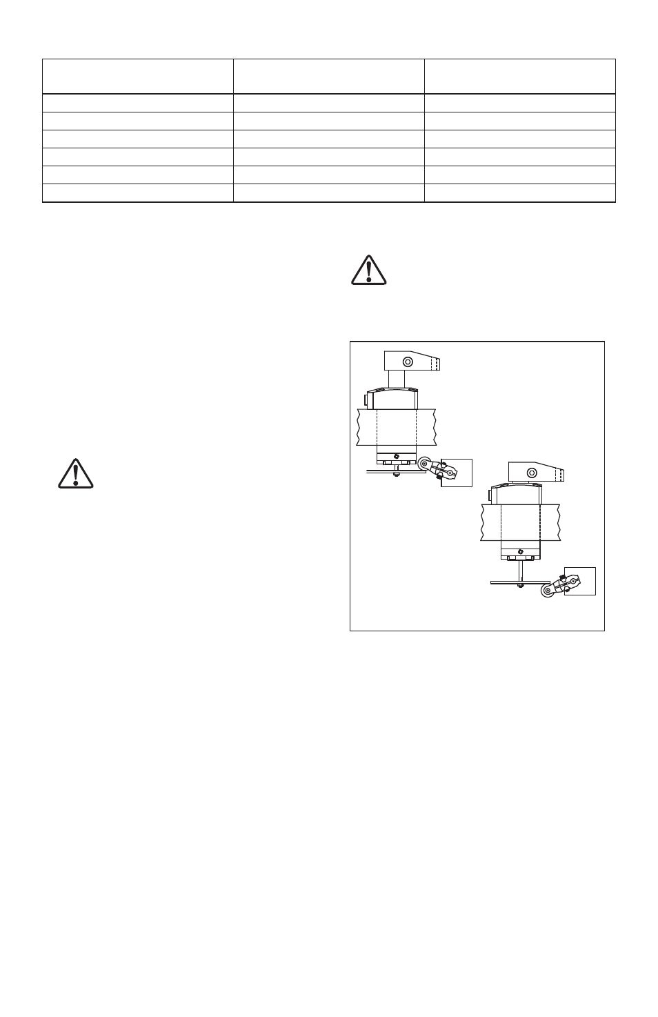
7.2 Position Indicating Staff
Enerpac 70 Bar Swing Cylinders are available with
a positioning indicating staff (optional equipment)
that anchors into the plunger and follows the plunger
movement. The indicating staff is designed for use with
either limit or proximity switches.
A suitable target or flag can be attached using the male
M4 x .07 mm threads on the staff end. See Figure 6.
Clearance below the clamp must be sufficient for the
extended portion of the staff to avoid damage.
CAUTION: It is very important that you use
the correct pressure and flow settings.
Operating outside these limits will cause
damage to the swing cylinder. Damage caused by
exceeding rated pressure and maximum flow is NOT
COVERED BY WARRANTY.
For
“Unclamp”
Detection
For
“Clamp”
Detection
Figure 6, Position Indicating Staff
8.0 MAINTENANCE
Maintenance is required when wear or leakage is
noticed. Periodically inspect all components to detect
any problem requiring service and maintenance.
Enerpac offers ready-to-use repair parts kits. Repair
parts sheets are available with assembly diagrams and
parts lists. Contact Enerpac.
IMPORTANT: Consult the swing cylinder repair parts
sheet for service information about correct assembly
and disassembly. Incorrect maintenance and service
such as wrong torque values may cause product
malfunctions and/or personal injury.
Table 13 - Maximum Contact Bolt Length
Cylinder Capacity
CAS Series Arm (See Fig. 5)
“P” Dimension
Maximum Contact Bolt Length
(See Fig. 5)
2,0 kN [441 lbs]
CAS-722
35,05 mm [1.38 inch]
14,48 mm [0.57 inch]
3,5 kN [769 lbs]
CAS-7352
53,09 mm [2.09 inch]
(unlimited)
5,0 kN [1111 lbs]
CAS-7352
53,09 mm [2.09 inch]
(unlimited)
7,0 kN [1570 lbs]
CAS-7792
55,63 mm [2.19 inch]
14,48 mm [0.57 inch]
9,0 kN [2019 lbs]
CAS-7792
55,63 mm [2.19 inch]
14,48 mm [0.57 inch]
20,0 kN [4490 lbs]
CAS-7202
68,07 mm [2.68 inch]
14,48 mm [0.57 inch]