Not recommended, Table 3 - clamp arm dimensions “m”, “n” and “p, 1 clamping force vs. arm length – Enerpac SU7-Series User Manual
Page 3
3
Table 4 - Clamping Force vs. Arm Length - 2 kN Models
Pressure
(bar)
Dimension “M” (See Graphic in Table 3)
Flange Face to Clamping Point - In Millimeters
10*
20
30
40
50
60
70
80
95**
Clamp
Force
(kN)
Clamp
Force
(kN)
Clamp
Force
(kN)
Clamp
Force
(kN)
Clamp
Force
(kN)
Clamp
Force
(kN)
Clamp
Force
(kN)
Clamp
Force
(kN)
Clamp
Force
(kN)
70
1,96
65
1,82
60
1,69
55
1,56
NOT RECOMMENDED
45
1,25
1,33
40
1,11
1,20
1,18
35
0,98
1,07
1,02
1,02
30
0,85
0,89
0,85
0,85
0,85
25
0,71
0,76
0,71
0,71
0,71
0,71
20
0,56
0,62
0,58
0,58
0,58
0,58
0,58
0,56
15
0,42
0,44
0,40
0,40
0,40
0,40
0,40
0,40
0,38
10
0,29
0,31
0,27
0,27
0,27
0,27
0,27
0,27
0,27
Maximum
Flow (lpm)
0,41
0,31
0,25
0,21
0,18
0,15
0,14
0,12
0,11
Notes: * CAS-722 standard arm ** CAL-722 long arm
Conversion Information: 1 mm = 0.039 in. 1 kN = 224.82 lbs. 1 bar = 14.5 psi 1 lpm = 61.02 in³/min
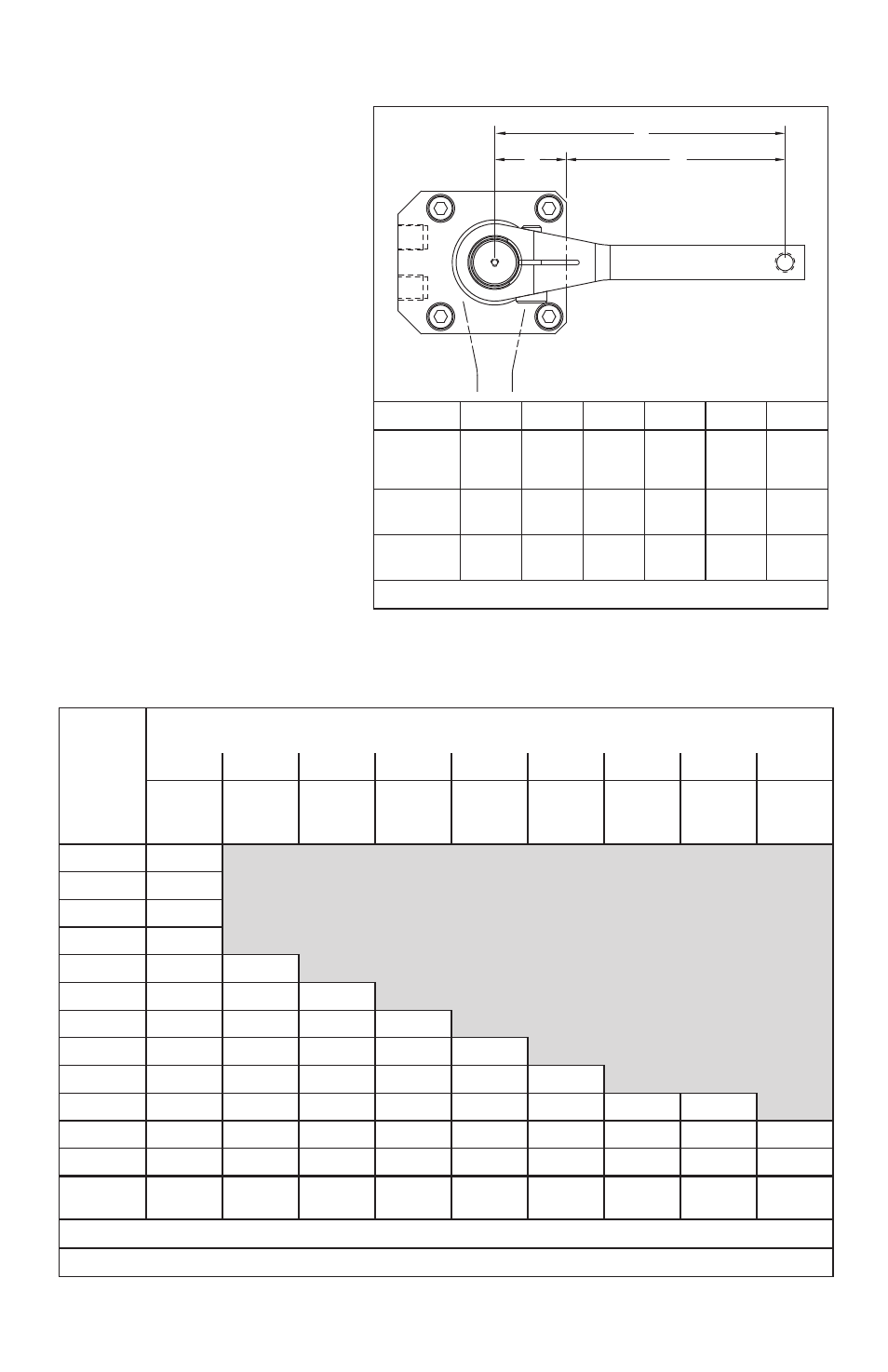
Table 3 - Clamp Arm Dimensions “M”, “N” and “P”
M
P
N
Size
2 kN
3,5 kN
5 kN
7 kN
9 kN
20 kN
Dimension
“M”
See
Table
4
See
Table
5
See
Table
6
See
Table
7
See
Table
8
See
Table
9
Dimension
“N”
25 mm
27 mm
30 mm
37 mm
38 mm
49 mm
Dimension
“P”
M + N
M + N
M + N
M + N
M + N
M + N
Conversion Information: 1 mm = 0.039 in.
3.1 Clamping Force vs.
Arm Length
Refer to the tables in this section when
selecting the swing cylinder model and
arm length for your application.
IMPORTANT: As the arm length
increases, the maximum allowable
pressure and flow rate decreases.
Exceeding these limits may cause
damage to the product. If the pressure
required for a desired clamping force
and arm length exceeds the specified
limits, select a higher capacity swing
cylinder model.
(REF)