Not recommended, 0 description, 1 preliminary information – Enerpac SU7-Series User Manual
Page 6
6
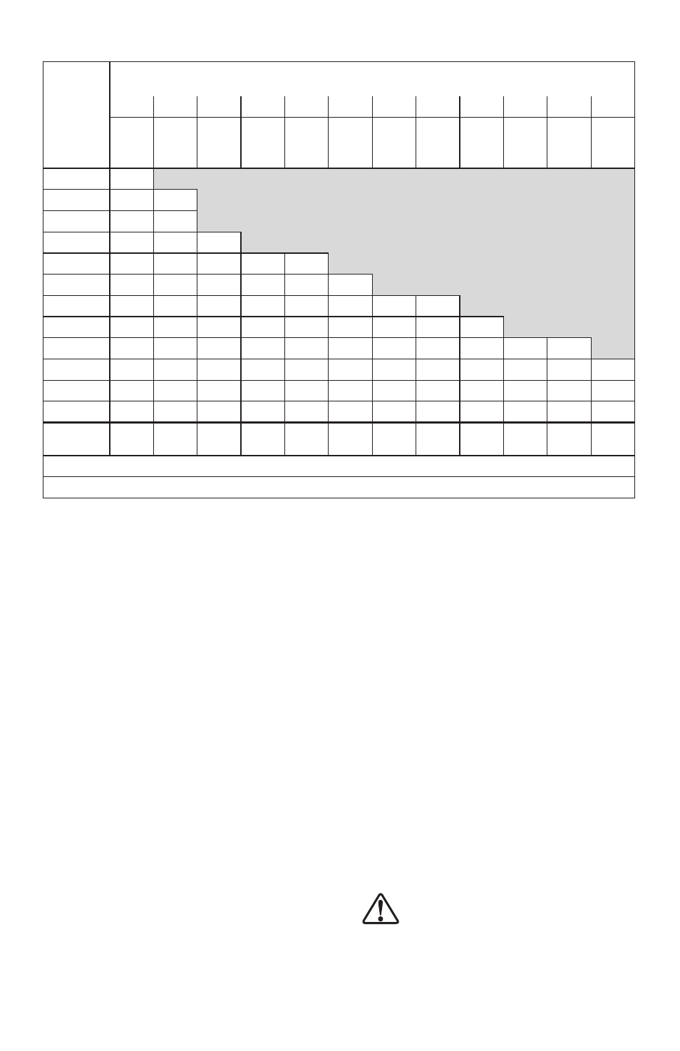
Table 9 - Clamping Force vs. Arm Length - 20 kN Models
Pressure
(bar)
Dimension “M” (See Graphic in Table 3)
Flange Face to Clamping Point - In Millimeters
19*
20
20
20
20
60
70
80
90
100
120
125**
Clamp
Force
(kN)
Clamp
Force
(kN)
Clamp
Force
(kN)
Clamp
Force
(kN)
Clamp
Force
(kN)
Clamp
Force
(kN)
Clamp
Force
(kN)
Clamp
Force
(kN)
Clamp
Force
(kN)
Clamp
Force
(kN)
Clamp
Force
(kN)
Clamp
Force
(kN)
70
19,97
65
18,64
19,79
60
17,21
18,24
55
15,79
16,72
16,41
NOT RECOMMENDED
45
12,90
13,70
13,30
13,30
13,26
40
11,48
12,19
11,70
11,70
11,70
11,65
35
10,05
10,63
10,10
10,10
10,05
10,05
10,01
10,01
30
8,58
9,12
8,67
8,67
8,67
8,67
8,63
8,63
8,63
25
7,16
7,61
7,16
7,16
7,12
7,12
7,12
7,07
7,03
6,98
6,98
20
5,74
6,09
5,74
5,74
5,74
5,74
5,74
5,69
5,65
5,60
5,60
5,56
15
4,31
4,58
4,27
4,27
4,27
4,23
4,23
4,23
4,23
4,18
4,18
4,14
10
2,85
3,02
2,8
2,80
2,80
2,78
2,76
2,76
2,76
2,76
2,76
2,71
Maximum
Flow (lpm)
4,10
4,05
3,71
3,42
3,17
2,96
2,77
2,61
2,47
2,33
2,22
2,16
Notes: * CAS-7202 standard arm ** CAL-7202 long arm
Conversion Information: 1 mm = 0.039 in. 1 kN = 224.82 lbs. 1 bar = 14.5 psi 1 lpm = 61.02 in³/min
4.0 DESCRIPTION
Enerpac 70 Bar swing cylinders are designed to
swing 90° in a clockwise or counter-clockwise
direction. Single-acting and double-acting models are
available. Clamp arms are not supplied with cylinders.
Clamp arms can be purchased separately or may be
fabricated according to the specifications in Section
10.0 of this manual.
4.1 Preliminary Information
IMPORTANT: Failure to read and follow these
instructions may lead to system malfunction or
product failure, and could invalidate your warranty.
1. High flow rates can lead to excessive cylinder
speed which can damage the index mechanism.
Hydraulic pressure and cylinder speed must be
adjusted to match the length of clamp arm. The
clamping force also varies with the length of the
clamp arm. Refer to sections 3.0 and 3.1 of this
manual for operating specifications and clamp arm
length information.
2. Flow controls with return checks should be used to
reduce swing cylinder speed to the recommended
rate. The return checks help minimize back pressure
that could lead to an unclamp malfunction on single-
acting systems.
3. When using single-acting swing cylinders, limit
the return flow back pressure to 3,5 bar [50 psi]
maximum. Large diameter tubing (10 mm [3/8 in.]
O.D. or larger) and flow controls with free flow
return checks help minimize back pressure. Consult
Enerpac for proper system design.
4. An excessive retract flow rate can cause damage
to the index mechanism. Double acting systems
should be set up with a metered-in flow control, with
a reverse check used in the clamp port.
5. Clamping of the part should occur at the midpoint
of the vertical travel. No clamping of part shall occur
while the swing cylinder clamp is turning. Clamp arm
should freely travel during the 90° rotation (avoid
contact with cutter heads, tools, etc.).
6. Attaching clamp arm to cylinder plunger must be
done according to the instructions in Section 6.4.
5.0 MOUNTING SPECIFICATIONS
5.1 Mounting Upper Flange Cylinders
The Enerpac 70 bar swing cylinders feature an upper
flange design. The cylinder can be mounted to the fixture
using the supplied mounting bolts. Oil can be supplied
to the cylinder using either the BSPP hydraulic ports on
the flange or the O-Ring manifold ports on the underside
of the flange. The sections that follow provide detailed
mounting instructions and should be reviewed before
attempting to install the cylinders on the fixture.
WARNING: The fixture must be capable of
withstanding 70 bar [1000 psi] hydraulic
working pressure when the cylinders are
manifold mounted.