Enerpac SU7-Series User Manual
Page 8
6.2 Hydraulic Connections
To make port connections, install fittings rated for 70
bar [1000 psi].
DO NOT use thread sealant. Sealing is accomplished
by using an O-Ring on the fitting boss. Lubricate the
O-Ring prior to assembly.
When designing your hydraulic circuit, consider
the factors listed in Section 4.1 of this manual.
For additional information about plumbing hydraulic
circuits, refer to the Enerpac Workholding product
catalog.
Table 11 - Cylinder Ports
Cylinder Capacity
BSPP Port Size
2,0 kN [441 lbs]
G ¹⁄
8
3,5 kN [769 lbs]
G ¹⁄
8
5,0 kN [1111 lbs]
G ¹⁄
8
7,0 kN [1570 lbs]
G ¼
9,0 kN [2019 lbs]
G ¼
20,0 kN [4490 lbs]
G ¼
6.3 Vent Plug
Single-acting cylinders have a vented plug on the left
side of the cylinder when you are facing the hydraulic
ports. To prevent entry of chips and coolant, the vent
plug must not be removed. If the vent plug is subjected
to a continuous coolant flood condition, attach tubing
to the port using a BSPP fitting, and run the tubing to a
non-contaminated area of the fixture.
6.4 Attaching Clamp Arm
1. Remove the retaining ring from the top of the
plunger.
2. Slide the clamp arm down over the plunger and
use a pliers to push the retaining ring back onto
the plunger groove. Orient the retaining ring so the
retaining ring gap will face the back of the clamp
arm. See Figure 4.
3. Move the clamp arm up until it is firmly against the
retaining ring and in the desired position. While
maintaining this position, torque the clamp arm bolt
to specification shown in Table 12.
Retaining
Ring
Plunger
Clamp Arm
Clamp Arm
Bolt
Figure 4, Attaching Clamp Arm
CAUTION: Inadequate torquing of the
clamp arm bolt could cause the arm to slip
during operation. BE SURE TO USE
QUALITY 12.9 DIN 912 (GRADE 8) SOCKET HEAD CAP
SCREWS (supplied with standard clamp arms).
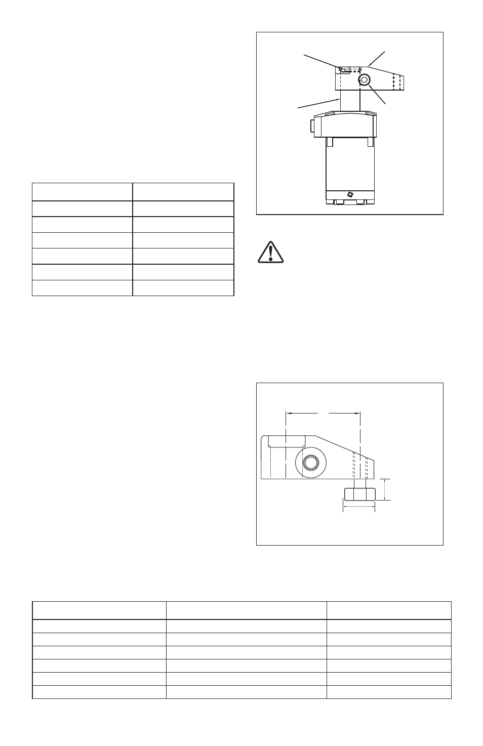
6.5 Contact Bolt Clearance
When using a contact bolt with upper flange body style
cylinders, you must be certain that the bolt head will
clear the cylinder upper flange during operation. The
clamp arm must be long enough for the bolt head to
clear the upper flange as the arm swings down. Refer to
Figure 5 and Table 13.
P
Note: Bolt head diameter
must not be larger than
16 mm [0.63 in.]
Max. Bolt Length
(see Table 13)
Figure 5, Contact Bolt Clearance
8
Table 12 - Clamp Arm Bolt Torque
Cylinder Capacity
Bolt Type
Torque
2,0 kN [441 lbs]
M8 x 1,0 x 20 mm long
32,5-39,0 Nm [24-29 ft-lbs]
3,5 kN [769 lbs]
M8 x 1,0 x 25 mm long
32,5-39,0 Nm [24-29 ft-lbs]
5,0 kN [1111 lbs]
M8 x 1,0 x 25 mm long
32,5-39,0 Nm [24-29 ft-lbs]
7,0 kN [1570 lbs]
M10 x 1,25 x 25 mm long
60,0-72,0 Nm [44-53 ft-lbs]
9,0 kN [2019 lbs]
M10 x 1,25 x 25 mm long
60,0-72,0 Nm [44-53 ft-lbs]
20,0 kN [4490 lbs]
M12 x 1.25 x 35 mm long
95,5-108,0 Nm [70-80 ft-lbs]
“P” Dimension - CAS Series Arm
(see Table 13)