Enerpac ZA4T-Series User Manual
Page 4
4
5.0 OPERATION
IMPORTANT: When possible, a single user should operate the
torque wrench and pump. This can prevent accidental activation
of the pump while the operator is positioning the wrench.
1. Check all system fi ttings and connections to be sure they are
tight and leak free.
2. Check oil level in reservoir and add oil
if necessary. (see section 4.4)
3. Make sure the shipping plug has
been removed and the breather cap is
installed. (see section 4.1)
WARNING: In the following
step, the pump motor will start
and the valve will shift
automatically, retracting the torque
wrench. Verify torque wrench is positioned
to avoid injury or equipment damage
before starting motor.
4. To start the pump, press the green
"ON/ADV" button (F) on the pendant (handset). The wrench
will advance as long as the green button is held down.
5. Release the green button to retract the wrench. The motor will
remain "ON".
6. Press the red "OFF" button (G) on the pendant to stop the
pump motor.
7.
To release hydraulic pressure on the wrench and hoses, press
and hold the red "OFF" button. Press and release the green
"ON/ADV" button 3 or more times until the pressure gauge
reads 0 pressure. The hoses can now be removed.
CAUTION: MAKE SURE THE MOTOR IS TURNED
OFF AND IS NOT RUNNING BY PRESSING THE RED
"OFF" BUTTON, BEFORE THE AIR SUPPLY SOURCE
IS TURNED OFF OR DISCONNECTED.
5.1 Air Removal
When the wrench is fi rst connected to the pump, air will be trapped
in the components. To ensure smooth and safe operation, remove
air by cycling wrench several times without load. Cycle until
wrench advances and retracts without hesitation.
Check oil level before operation.
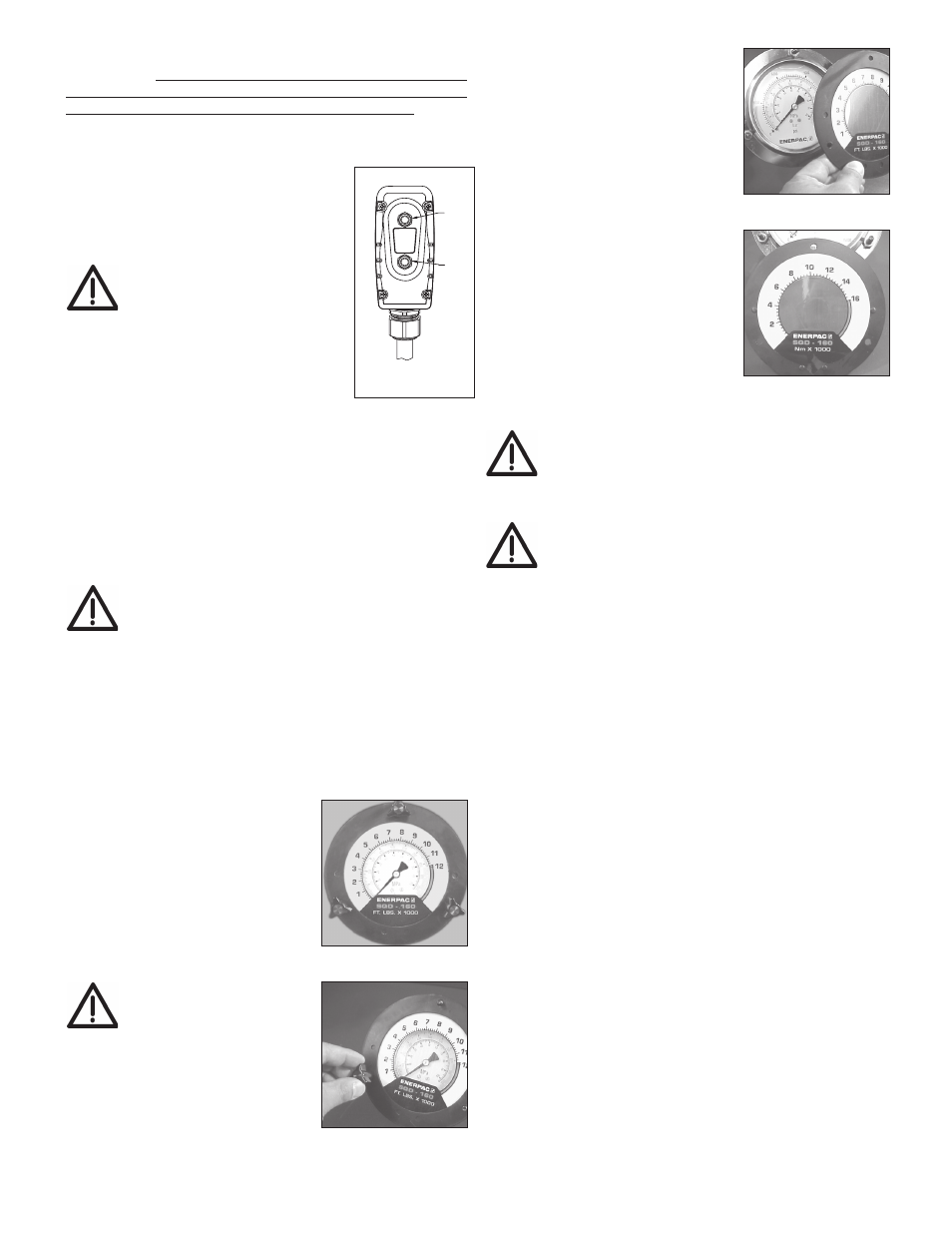
5.2 Gauge and Overlay Operation Procedure
The pump is supplied with a
pressure gauge installed. For your
convenience, torque overlays are
provided with each pump. A torque
overlay fi ts over the pressure gauge
dial face and easily converts pressure
readings to torque readings (see Fig.
8). The overlay has imperial units (Ft-
Lbs.) on one side and metric units
(Nm) on the other. To change scales
simply slip overlay over.
WARNING: Each overlay
is sized for a specifi c
Enerpac torque wrench
ONLY. Do not use with other
wrenches.
5.3 Changing the Overlay
1. Remove the three black wing
knobs which hold the front
gauge fl ange in place (see Fig. 9).
2. Remove the front fl ange and
overlay (see Fig. 10.)
3. Insert new overlay (remember to
verify correct overlay to the Enerpac
torque wrench being used) onto the
fl ange, aligning the overlay with the
dimples on the back of the fl ange
(see Fig. 11).
4.
While holding the overlay behind the
fl ange (see Fig. 10.) insert the fl ange
onto the knob studs, repositioning
the overlay as needed, and secure
knobs fi nger tight (see Fig. 9).
The fl ange will press the overlay
onto the gauge and secure it
in place. See torque wrench
instructions for amount of pressure
required to produce desired torque.
Note that the maximum pressure
varies for diff erent wrenches and
accessories.
CAUTION: Refer to torque wrench instructions for
wrench operating procedure.
5.4 Pressure (Torque) Setting
WARNING: Make these adjustments BEFORE putting
torque wrench on nut or bolt head. The pump pressure
setting may not be above the pressure needed to
provide the required torque for your application. Exceeding
required torque will cause equipment damage and may lead to
serious personal injury.
To limit the advance pressure to the torque wrench, adjust the
relief valve as described in the following procedure. See Figure 12.
1. Loosen the relief valve locking nut.
2. Rotate relief valve handle counter-clockwise as required, until
there is little or no resistance when turning. When this occurs,
the valve is at its lowest setting.
Note: Relief valve handle will rotate only about two thirds of a full
turn. When rotation stops, pull up on handle to disengage. Then,
reposition and re-engage handle to allow additional adjustment
(as required).
3.
Press and hold the pendant “ON/ADV” button. Motor will start
and pressure will begin building in the A-Port advance circuit.
4.
While continuing to hold down the “ON/ADV” button, SLOWLY
rotate relief valve handle clockwise, until pressure increases
to the desired setting.
Note: To obtain an accurate setting, always decrease the pressure
to a point below the fi nal setting and then slowly increase the
pressure until the fi nal setting is reached.
5.
Release the “ON/ADV” button to allow the system pressure to
return to the B-port retract setting. The motor will continue to
run.
6. Press and hold the “ON/ADV” button again to recheck the
advance circuit pressure setting. Verify that the desired
pressure is indicated on the pressure gauge.
7. After the desired pressure setting has been obtained, tighten
the relief valve locking nut.
F
G
OFF
ON/ADV
Figure 7
Figure 8
Figure 9
Figure 10
Figure 11