Elkhart Brass Cobra 7200 EXM Monitor User Manual
Page 16
16
EXM CAN Stow Module –
Using the EXM CAN Stow Module template shown in the Component Mounting Templates
section, drill the two (2) 1/4” dia. holes through the surface intended for mounting.
Mount the Stow Module using two (2) 1/4” dia. fasteners secured with blue Loctite 242 or
equivalent.
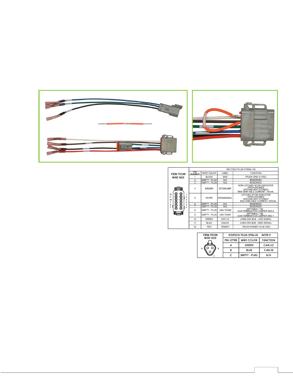
Connect Plug 2 leads to the appropriate CAN line.
o
If the Stow Module will be a termination point (at the extreme end of your main CAN
line), install the supplied jumper between positions 8 & 9 of the Stow Module Harness.
Connect the Stow indicator leads of the Stow
Module Harness to the customer supplied
devices that the Stow Module is to actuate.
o
The Stow Module provides a ground to these
leads when the EXM monitor is not stowed,
and provides an open circuit otherwise.
o
The Stow Lamp lead (position 4) can be
used to switch a light or device with a low
current draw. There is a 100ohm current-
limiting resistor on this signal so that this
lead could be directly connected to an
LED. (Seal lead if unused)
o
The Stow Signal lead (position 5) can be used to switch a device that may require more
current or one that you want to maintain the switch state when the Stow Module is
powered off. (Seal lead if unused)
Supply power to the Stow Module by connecting the RED (power) and BLACK (ground) leads to
an appropriate power source.
Install a 1 Amp fuse into the positive power lead for a 12V system (1/2 Amp for 24V system).
2a
1
2b
1
2
Jumper
Jumper