Despatch MIC1422 Controller User Manual
Page 19
15
FIGURE 2-11
Remote Digital Communications - RS485
Make digital communication connections as illustrated below.
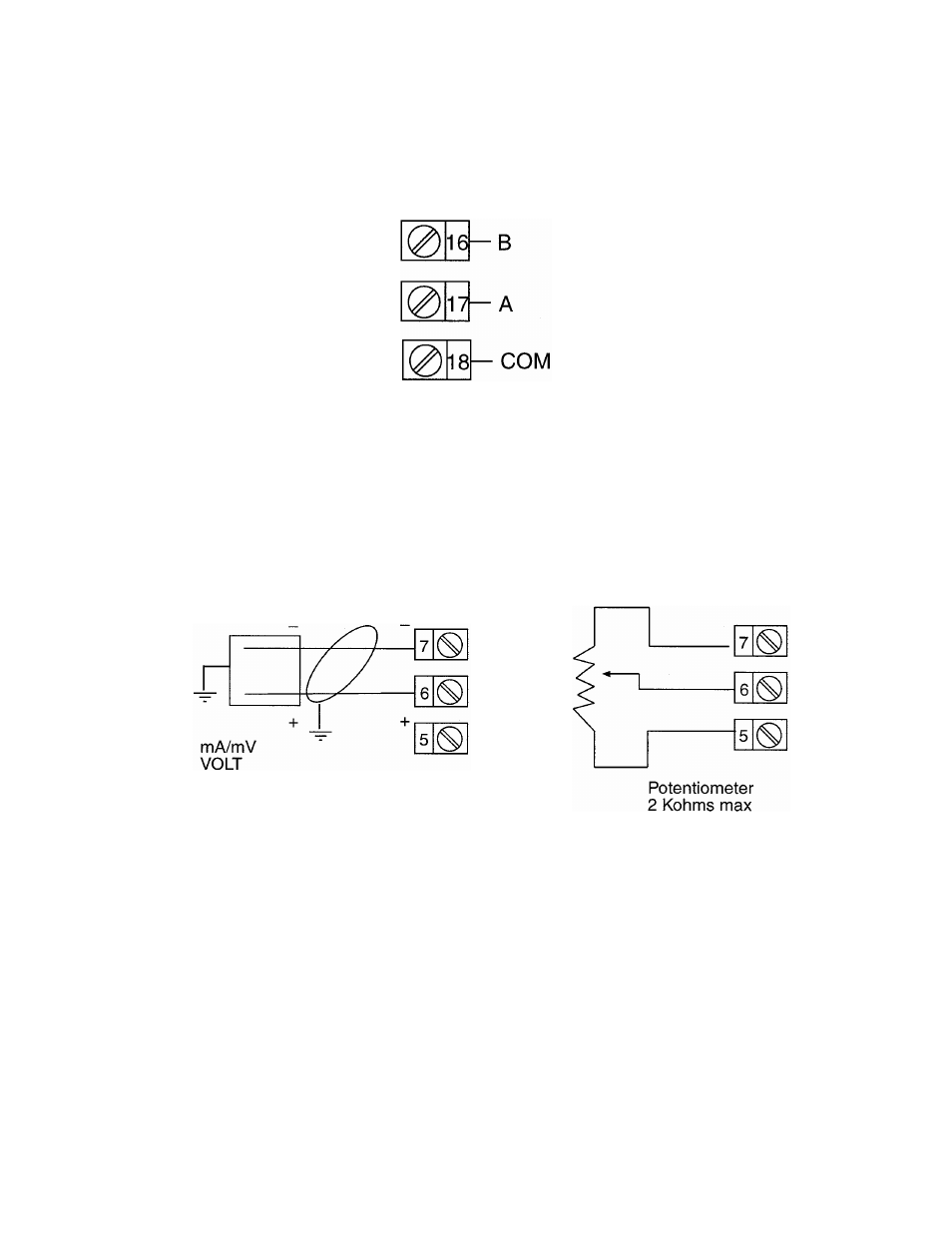
FIGURE 2-12
Remote Setpoint Input - V/mA/mV and Potentiometer
Connections are illustrated below. Terminal 6 is positive and terminal 7 is negative.
The remote setpoint input can be configured for linear DC mv, linear DC mA, linear DC
Volt or potentiometer. Make sure that the input selected matches the Second Input
Usage selected in the Hardware Definition Mode and the Secondary Analog Input
conditioning jumper is positioned correctly (see Appendix A.)