Dakota Ultrasonics PVX User Manual
Page 73
PVX Precision Visual Thickness Gauge
69
The most straight forward way of setting up the PVX for thru paint measurements is
to select a factory setup with a corresponding transducer type from the list of setups
included with the PVX. These setups will serve as a good starting point for setting
customized applications. However, fine adjustments may be necessary in order to be
suitable for your specific applications. These configurations are general setups only,
but have been setup and optimized for the majority of common measurement. Once
a setup has been selected and the appropriate calibration procedure completed, the
user can make any fine adjustments to the setup and begin taking measurements.
When configuring the PVX for specific thru paint applications, all of the scope
parameters will potentially be needed. The delay, width, gain, threshold, gate1, and
gate2 features will be subject to change. For this reason, they have all been added
to Hot Menu fields located directly beneath the A-Scan display for quick and easy
access. Note: Once the values of the fields have been changed or modified, these
changes must be saved to a setup location prior to powering the PVX off. Failure to
do so will result in losing your changes.
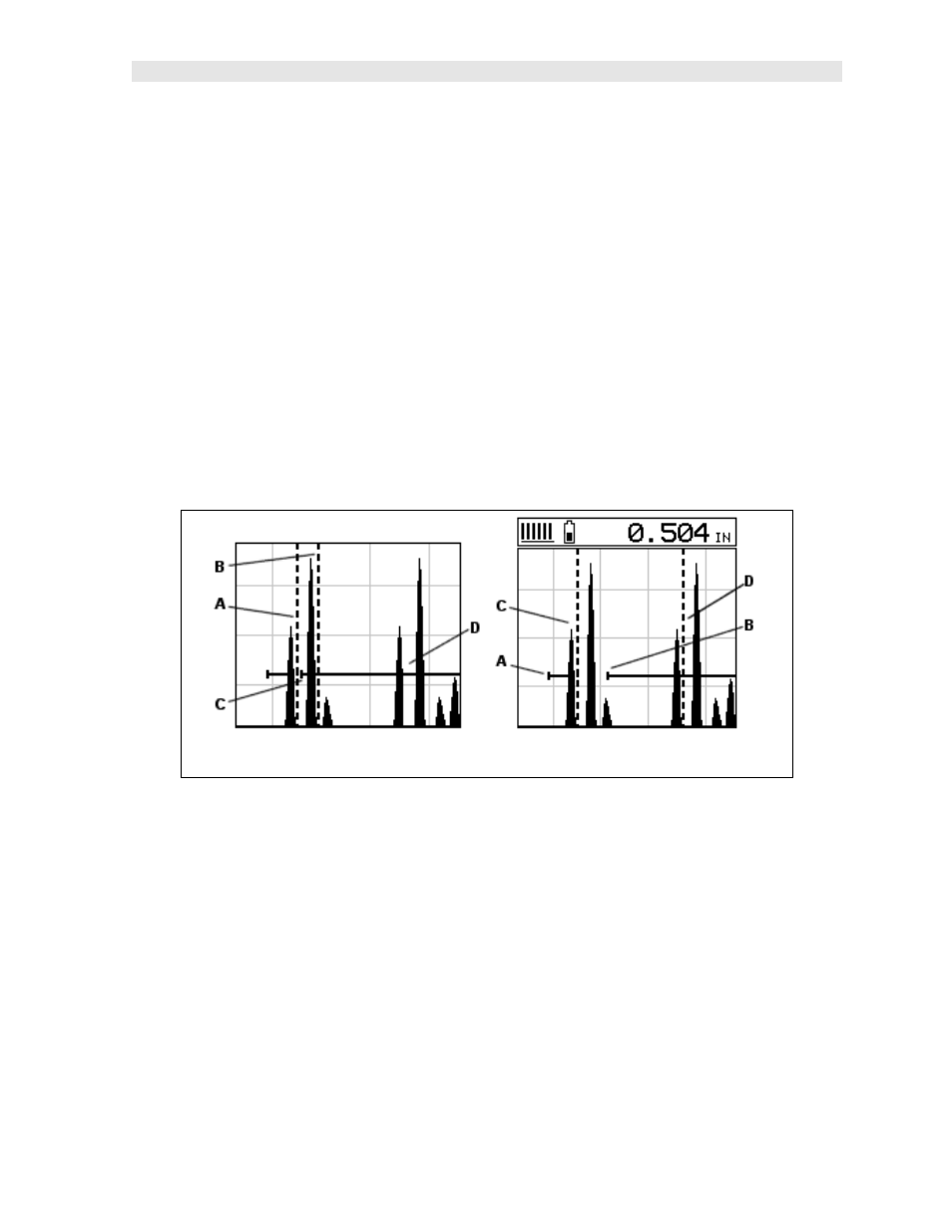
THRU-PAINT (INCORRECT) THRU-PAINT (CORRECT)
Refer to the incorrect diagram above. Point (A) represents the detection on the first
back wall echo. The true, second back wall, reflection should be detecting at point
(D). However, the hold-off (C) is setup incorrectly and the PVX is detecting the ring
down noise of the transducer, on the first reflection, rather than the true second back
wall reflection shown at (D).
Before we look at the diagram with the correct configuration, let’s consider all of our
options on how to fix the problem beforehand. Our delay and width will simply
change the view options of the screen – not needed in this e xample. Will a gain or
threshold adjustment fix the problem? Unfortunately, not. Why? Notice the
amplitude of the cycle just to the left of (B). If we tried to increase the threshold level
above the height of the cycle, we would lose our detection for both echoes resulting
in no reading at all. If we decrease our gain , reducing the signal amplitudes, we
would also lose our detection of both back wall echoes.