COATS M-61 Wheel Balancer User Manual
M-61 operating instructions
8113006 00 05/09
© COPYRIGHT 2004 ALL RIGHTS RESERVED PRINTED IN U.S.A.
Instructions
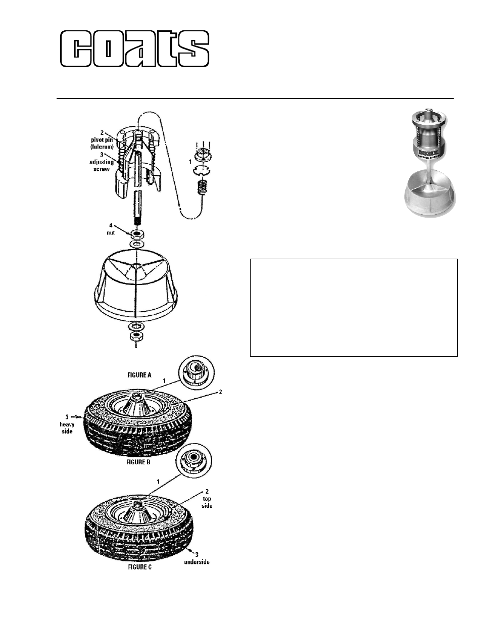
1. Assemble the M-61 wheel balancer as
shown in figure A.
2. After assembling the wheel balancer,
view the circular level (bubble) at the top of
the bead. See arrow 1, figure B. Make certain
the bubble rests in the middle of the
black circle before using the balaner.
Adjustments are made while the head
rests on the support shaft (X-065). The
bubble on the M-61 wheel balancer is
mounted onto the top of the head assembly
cone by three (3) adjusting screws. Take care to make cer-
tain that the bubble rests squarely in the center of the black
circle.
3. Remove the tire and wheel from the vehicle. Clean off
any debris from the inside/underside of the rim. Check the
hub hole on the rim to insure that it is clean to allow for uni-
form seating on the balancer cone (head assy.).
Place the tire/wheel assembly on the balancer. Listen for
uniform seating when tire/wheel assy. engages cone. Let
the tire/wheel settle to a stop.
There exists an out-of-balance condition when the heavy
side of the tire/wheel causes the bubble to move outside
the black circle in the opposite direction from the heavy
side. See arrow 1, figure B.
Place a weight on the light side of the rim closest to the
bubble. See arrow 2, figure B. If the first weight does not
bring the bubble back to the middle of the black circle, then
try a larger (heavier) weight , or a smaller (lighter) weight to
bring the bubble into the middle of the circle as shown in
arrow 1, figure C.
4. Remove the tire/wheel from the balancer and place
the proper amount of weight needed equally on both sides
of the wheel, attach 1 1/2 ounce weight on the top of the
wheel rim and 1 1/2 ounce weight on the underside of the
wheel rim at the same location.
M-61 Operating Instructions
COATS, Inc. • Hennessy Industries • 1601 J.P. Hennessy Drive, LaVergne, TN 37086-3565
(800) 688-6359 • (615) 641-7533 • (615) 641-5104 FAX • www.ammcoats.com
Care and Maintenance
1) Always keep No. 10 weight oil (or equivalent) around
the pivot pin located in the upper end of the support
shaft (X-065). [Arrow 2, Fig. A]
2) Make certain the four (4) guide posts on the head
assembly are free of dirt and debris and kept treated
with a light lubricant.
3) Keep dirt and any foreign materials from gathering on
bottom flange of the head assembly.