Installation, Alarm i/o connection, Loosen the screws on both the alarm input port and – CCTV Camera Pros iDVR-PRO H Series DVRs User Manual
Page 20: Port of the provided terminal block plug, Insert one end of alarm signal cable through the, Insert the ground signal wire into the hole of the, Port, Loosen the screws on the, Ports and the, Insert the alarm signal wire into the hole of the
Installation
20
|
Installation
\
\
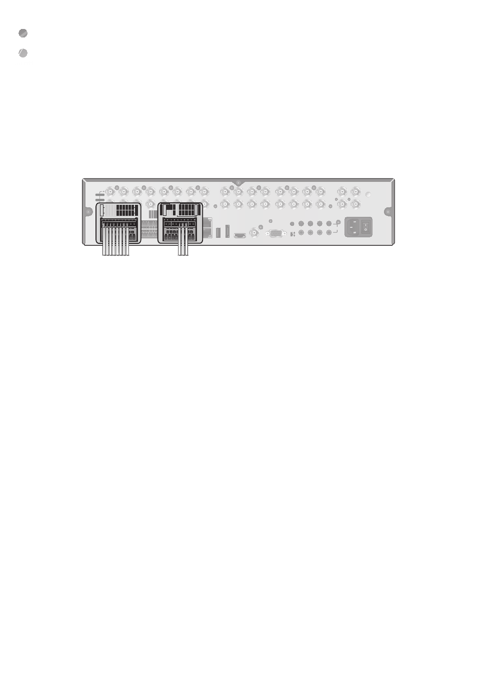
Alarm I/O Connection
To connect the alarm input signal
Connect the signal line of an alarm input device such as sensor to the rear [ALARM IN] port.
1.
Loosen the screws on both the alarm input port and [
GND
] port of the provided terminal block plug.
2.
Insert one end of alarm signal cable through the [
AO1
] or [
AO8
] terminal hole below the screw hole, and then fasten
the screw.
3.
Insert the ground signal wire into the hole of the [
GND
] port (shown also below the screw), and tighten the screw.
4.
To check proper insertion of cable, stop pushing and gently pull the cable and test whether it disconnects.
To disconnect a cable, push the bottom side of the terminal and pull out the cable.
To connect the alarm output signal
Connect the signal line of an alarm output device to the rear [
RELAY
] port.
1.
Loosen the screws on the [
NO
] and [
NC
] ports and the [
COM
] port of the provided terminal block plug.
2.
Insert the alarm signal wire into the hole of the [
NO
] or [
NC
] input port (shown below the screw), and tighten the
screw.
Check the relay output type of Normal Open or Normal Close before selecting a proper type (NO or NC).
i
NO(Normal Open) : Normally Open but switching to Close if an alarm out occurs.
i
COM : Insert the grounding wire.
i
NC(Normal Close) : Normally Close but switching to Open if an alarm out occurs.
3.
Insert the ground signal wire into the hole of the [COM] port (shown also below the screw), and tighten the screw.
Or, you can connect the signal cable of the alarm output device to the [ALARM OUT] port on the rear side.
1.
Loosen the screws on the [
AO1
] and [
AO8
] ports and the [
GND
] port of the provided terminal block plug.
2.
Insert the alarm signal wire into the hole of the [
AO1
] or [
AO8
] input port (shown below the screw), and tighten the
screw.
Check the relay output type of Normal Open or Normal Close before selecting a proper type (NO or NC).
3.
Insert the ground signal wire into the hole of the [
GND
] port (shown also below the screw), and tighten the screw.
4.
To check proper insertion of cable, stop pushing and gently pull the cable and test whether it disconnects.
To disconnect a cable, push the bottom side of the terminal and pull out the cable.
5.
Install the wire-connected terminal block in the rear port.
RELA
Y
NO3
NO1
COM3
COM1
COM4
COM2
NC4
NC2
IN5
IN1
IN6
IN2
GND
GND
IN7
IN3
IN8
IN4
GND
ARI
ALARM IN
RELA
Y
NO7
NO5
COM7
COM5
COM8
COM6
NC8
NC6
IN3
IN9
IN14
IN10
GND
GND
IN15
IN11
IN16
IN12
GND
PANIC
ALARM IN
RS-485_1
ALARM OUT
RS-485_2
D+
D+
D-
D-
GND
GND
RX
TX
AO5
AO1
AO6
AO2
GND
GND
AO7
AO3
AO8
AO4
RS-232
LAN
(DOWNLINK)
WAN
(UPLINK)
eSATA
USB
HD MONITOR
AUX
VGA
NTSC
PAL
1
2
3
4
5
6
7
8
9
10
11
12
13
14
15
16
1 / 2
1 / 2
5 / 6
9 / 10
13 / 14
3 / 4
7 / 8
11 / 12
15 / 16
AUDIO OUT
AUDIO IN
ON
OFF
100-240V - 50/60 Hz
SPOT 1
SPOT 2
SPOT 3
SPOT 4
VIDEO IN
LOOP OUT
RELA
Y
NO3
NO1
COM3
COM1
COM4
COM2
NC4
NC2
IN5
IN1
IN6
IN2
GND
GND
IN7
IN3
IN8
IN4
GND
ARI
ALARM IN
RELA
Y
NO7
NO5
COM7
COM5
COM8
COM6
NC8
NC6
IN3
IN9
IN14
IN10
GND
GND
IN15
IN11
IN16
IN12
GND
PANIC
ALARM IN
RS-485_1
ALARM OUT
RS-485_2
D+
D+
D-
D-
GND
GND
RX
TX
AO5
AO1
AO6
AO2
GND
GND
AO7
AO3
AO8
AO4
RS-232
LAN
(DOWNLINK)
WAN
(UPLINK)
eSATA
USB
HD MONITOR
AUX
VGA
NTSC
PAL
1
2
3
4
5
6
7
8
9
10
11
12
13
14
15
16
1 / 2
1 / 2
5 / 6
9 / 10
13 / 14
3 / 4
7 / 8
11 / 12
15 / 16
AUDIO OUT
ON
OFF
100-240V - 50/60 Hz
SPOT 1
SPOT 2
SPOT 3
SPOT 4
VIDEO IN
LOOP OUT
AUDIO IN
RELA
Y
NO3
NO1
COM3
COM1
COM4
COM2
NC4
NC2
IN5
IN1
IN6
IN2
GND
GND
IN7
IN3
IN8
IN4
GND
ARI
ALARM IN
RELA
Y
NO7
NO5
COM7
COM5
COM8
COM6
NC8
NC6
IN3
IN9
IN14
IN10
GND
GND
IN15
IN11
IN16
IN12
GND
PANIC
ALARM IN
RS-485_1
ALARM OUT
RS-485_2
D+
D+
D-
D-
GND
GND
RX
TX
AO5
AO1
AO6
AO2
GND
GND
AO7
AO3
AO8
AO4
RS-232
LAN
(DOWNLINK)
WAN
(UPLINK)
eSATA
USB
HD MONITOR
AUX
VGA
NTSC
PAL
1
2
3
4
5
6
7
8
9
10
11
12
13
14
15
16
1 / 2
1 / 2
5 / 6
9 / 10
13 / 14
3 / 4
7 / 8
11 / 12
15 / 16
AUDIO OUT
ON
OFF
100-240V - 50/60 Hz
SPOT 1
SPOT 2
SPOT 3
SPOT 4
VIDEO IN
LOOP OUT
RELA
Y
NO3
NO1
COM3
COM1
COM4
COM2
NC4
NC2
IN5
IN1
IN6
IN2
GND
GND
IN7
IN3
IN8
IN4
GND
ARI
ALARM IN
RELA
Y
NO7
NO5
COM7
COM5
COM8
COM6
NC8
NC6
IN3
IN9
IN14
IN10
GND
GND
IN15
IN11
IN16
IN12
GND
PANIC
ALARM IN
RS-485_1
ALARM OUT
RS-485_2
D+
D+
D-
D-
GND
GND
RX
TX
AO5
AO1
AO6
AO2
GND
GND
AO7
AO3
AO8
AO4
RS-232
LAN
(DOWNLINK)
WAN
(UPLINK)
eSATA
USB
HD MONITOR
AUX
VGA
NTSC
PAL
1
2
3
4
5
6
7
8
9
10
11
12
13
14
15
16
1 / 2
1 / 2
5 / 6
9 / 10
3 / 4
7 / 8
11 / 12
AUDIO OUT
VIDEO IN
LOOP OUT
RELA
Y
NO3
NO1
COM3
COM1
COM4
COM2
NC4
NC2
IN5
IN1
IN6
IN2
GND
GND
IN7
IN3
IN8
IN4
GND
ARI
ALARM IN
RELA
Y
NO7
NO5
COM7
COM5
COM8
COM6
NC8
NC6
IN3
IN9
IN14
IN10
GND
GND
IN15
IN11
IN16
IN12
GND
PANIC
ALARM IN
RS-485_1
ALARM OUT
RS-485_2
D+
D+
D-
D-
GND
GND
RX
TX
AO5
AO1
AO6
AO2
GND
GND
AO7
AO3
AO8
AO4
RS-232
LAN
(DOWNLINK)
WAN
(UPLINK)
eSATA
USB
HD MONITOR
AUX
VGA
NTSC
PAL
2
3
4
5
6
7
8
9
10
11
12
13
14
15
16
1 / 2
1 / 2
5 / 6
9 / 10
13 / 14
3 / 4
7 / 8
11 / 12
15 / 16
AUDIO OUT
AUDIO IN
SPOT 1
SPOT 2
RELA
Y
NO3
NO1
COM3
COM1
COM4
COM2
NC4
NC2
IN5
IN1
IN6
IN2
GND
GND
IN7
IN3
IN8
IN4
GND
ARI
ALARM IN
RELA
Y
NO7
NO5
COM7
COM5
COM8
COM6
NC8
NC6
IN3
IN9
IN14
IN10
GND
GND
IN15
IN11
IN16
IN12
GND
PANIC
ALARM IN
RS-485_1
ALARM OUT
RS-485_2
D+
D+
D-
D-
GND
GND
RX
TX
AO5
AO1
AO6
AO2
GND
GND
AO7
AO3
AO8
AO4
RS-232
LAN
(DOWNLINK)
WAN
(UPLINK)
eSATA
USB
HD MONITOR
AUX
VGA
NTSC
PAL
2
3
4
5
6
7
8
9
10
11
12
13
14
15
16
1 / 2
1 / 2
5 / 6
9 / 10
13 / 14
3 / 4
7 / 8
11 / 12
15 / 16
AUDIO OUT
AUDIO IN
SPOT 1
SPOT 2