Prepare site • prepare burner • mount burner, Model 601gas burner — instruction manual, Prepare burner and components – Carlin 601GAS Inst Manual User Manual
Page 9: Figure 3a tube/head configurations, typical
Model 601GAS burner — Instruction manual
Carlin part number MN601GAS Rev. 04/24/09
– 9 –
Where appliance instructions differ from this manual, follow the appliance instructions.
1. Prepare site • prepare burner • mount burner
(continued)
Table 1a Burner orifice sizing and starting air settings
Input
Note 1
B-Tube with 11-Head
C-Tube with 21-Head
D-Tube with 32-Head
Burner orifice
drill size
Inches
Approximate
air settings
Notes 1 & 2
Burner orifice
drill size
Inches
Approximate
air settings
Notes 1 & 2
Burner orifice
drill size
Inches
Approximate
air settings
Notes 1 & 2
Btuh
Natural
gas
Propane
gas
Air damper
position
Natural
gas
Propane
gas
Air damper
position
Natural
gas
Propane
gas
Air damper
position
700,000
19/32
(.5937)
7/16
(.4375)
0.5
NA
NA
NA
NA
NA
NA
750,000
5/8
(.6250)
15/32
(.4687)
2
NA
NA
NA
NA
NA
NA
800,000
21/32
(.6562)
31/64
(.4843)
2.25
21/32
(.6562)
1/2
(.5000)
closed
NA
NA
NA
850,000
11/16
(.6875)
1/2
(.5000)
3.75
11/16
(.6875)
33/64
(.5156)
0.5
NA
NA
NA
900,000
23/32
(.7187)
17/32
(.5312)
4
23/32
(.7187)
17/32
(.5312)
1
11/16
(.6875)
35/64
(.5469)
closed
950,000
25/32
(.7812)
35/64
(.5469)
7
3/4
(.7500)
35/64
(.5469)
1.5
23/32
(.7187)
9/16
(.5625)
0.5
1,000,000
7/8
(.8750)
9/16
(.5625)
open
27/32
(.8437)
9/16
(.5625)
2.5
3/4
(.7500)
19/32
(.5937)
1
1,050,000
NA
NA
NA
1
(1.000)
19/32
(.5937)
3
25/32
(.7812)
39/64
(.6049)
2.25
1,100,000
NA
NA
NA
NA
NA
NA
13/16
(.8125)
5/8
(.6250)
2.5
1,150,000
NA
NA
NA
NA
NA
NA
27/32
(.8437)
NA
3
1,200,000
NA
NA
NA
NA
NA
NA
7/8
(.8750)
41/64
(.6406)
4
1,250,000
NA
NA
NA
NA
NA
NA
15/16
(.9375)
NA
5
1,300,000
NA
NA
NA
NA
NA
NA
31/32
(.9687)
21/32
(.6562)
5.5
1,350,000
NA
NA
NA
NA
NA
NA
1 (1.000)
11/16
(.6875)
6
1,400,000
NA
NA
NA
NA
NA
NA
1 1/16
(1.063)
23/32
(.7187)
6.5
1,450,000
NA
NA
NA
NA
NA
NA
1 1/8
(1.125)
3/4
(.7500)
8.75
1,500,000
NA
NA
NA
NA
NA
NA
1 1/4 (1.25)
23/32
(.7182)
open
Note 1
Ratings:
• All ratings above are based on sea level.
• Altitude ratings: Reduce maximum capacity by 4% per 1,000 feet above sea level.
— Example: The maximum “B”-tube/head capacity at 5,000 feet altitude is 560,000 Btuh instead of 700,000, a 20% reduction.
Positive overfire pressure effects:
• Maximum burner input decreases with increasing overfire pressure.
• Assume a reduction in maximum burner input of approximately 5% at 0.1 inches w.c. and 10% at 0.2 inches w.c.
• You will have to increase the air damper opening to compensate for the increased pressure.
• Follow the procedures given in this manual to check combustion with instruments to determine the correct air setting.
• Never fire at a higher overfire pressure than recommended by the appliance manufacturer.
Note 2
Use air settings for starting only. Adjust air setting, if necessary, after performing combustion testing (see page 18).
Prepare burner and components
Do not install or operate the burner if any component is damaged
or if burner does not comply with the specifications of Table 1a
and other guidelines in this manual.
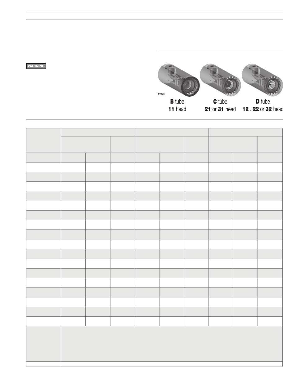
Combustion head/air tube configurations
• 601GAS burners are supplied with one of three tubes and one of three
heads, determined by firing rate and appliance application. Tubes are
specified as one of three configurations (B, C or D). Heads are specified
as type 11, 12, 21, 22, 31 or 32.
Figure 3a Tube/head configurations, typical