Prepare site • prepare burner • mount burner, Model 601gas burner — instruction manual, Prepare burner and components – Carlin 601GAS Inst Manual User Manual
Page 10
Model 601GAS burner — Instruction manual
Carlin part number MN601GAS Rev. 04/24/09
– 10 –
Where appliance instructions differ from this manual, follow the appliance instructions.
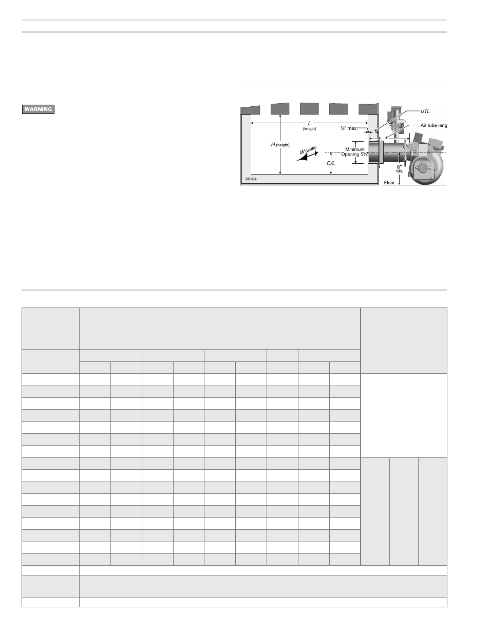
Figure 3b Chamber dimensions & tube configurations
Table 1b Minimum combustion chamber dimenions (see Figure 3b)
Prepare burner and components
Do not install or operate the burner if any component is damaged
or if burner does not comply with the specifications of Table 1b
and other guidelines in this manual.
Combustion chamber minimum dimensions
• For applications that have not been specifically tested (OEM applications),
verify that the combustion chamber provides the minimum dimensions
shown in Table 1b and Figure 3b. For specific OEM applications, the
appliance testing ensures suitability of the chamber.
• Chamber dimensions may be larger than listed in Table 1b, but should not
be excessively large.
Air tube insertion length (UTL)
• Usable air tube length (UTL) is the distance from mounting flange to end
of air tube. Verify that the end of the air tube will be flush with, or no more
than ¼ inch short of, the inside of the appliance combustion chamber front
wall when the burner is mounted. See Figure 3b and Table 1b for further
information.
Input
Note 1
Minimum chamber dimensions
Inches (Notes 1, 2, 3)
(VC = min. diam. of vertical cylinder chamber)
“Dry” means chamber surfaces refractory lined
“Wet” means water-back chamber surfaces, with no refractory covering
UTL
Air tube
insertion length
Btuh
L
W
C/L
H
VC
Dry
Wet
Dry
Wet
Dry
Wet
Wet
Dry
Wet
700,000
18
22
16
18
7.5
8.5
19
16
22
Welded flange:
Burners with welded flange have fixed
usable tube length (UTL) set for the
appliance application. Verify length is
correct for the application.
Adjustable flange:
Burners with adjustable flange:
Usable tube length (UTL) varies with air
tube length (see below).
750,000
19
23
16
18
7.5
8.5
19
17
23
800,000
20
24
17
19
8.0
9.0
20
18
24
850,000
20
24
17
19
8.0
9.0
20
18
24
900,000
22
27
17
19
8.0
9.0
20
20
27
950,000
24
29
17
19
8.0
9.0
20
22
29
1,000,000
24
29
17
19
8.0
9.0
20
22
29
1,050,000
27
33
17
19
8.0
9.0
20
25
33
Nominal
air tube
length
---------
14” B
14” C
14” D
UTL
min.
---------
1 ¾”
0”
0”
UTL
max.
---------
9”
7 ½”
7 ½”
1,100,000
30
36
17
19
8.0
9.0
20
28
36
1,150,000
31
38
17
19
8.0
9.0
20
29
38
1,200,000
31
38
17
19
8.0
9.0
20
29
38
1,250,000
33
40
17
19
8.0
9.0
20
31
40
1,300,000
35
42
17
19
8.0
9.0
20
33
42
1,350,000
35
42
17
19
8.0
9.0
20
33
42
1,400,000
38
46
18
20
8.5
9.5
21
36
46
1,500,000
42
50
18
20
8.5
9.5
21
40
50
Note 1
Some tested appliances may operate satisfactorily with dimensions less than the above.
Note 2
Horizontal cylindrical chambers — diameter must be no less than column “W” above
Horizontal stainless steel cylindrical chambers — diameter at least 1 to 4 inches larger than column “W” above.
VC is the minimum diameter for vertical cylindrical chambers (refractory or refractory-lined chambers only).
Note 3
A corbel may help heat transfer in a larger boiler or furnace, provided it is recommended by the appliance manufacturer.
1. Prepare site • prepare burner • mount burner
(continued)