Wire burner, Model 601gas burner — instruction manual, General wiring requirements – Carlin 601GAS Inst Manual User Manual
Page 14: Verify power supply, Wire to the burner, Checking burner flame signal, Code compliance
Model 601GAS burner — Instruction manual
Carlin part number MN601GAS Rev. 04/24/09
– 14 –
Where appliance instructions differ from this manual, follow the appliance instructions.
3. Wire burner
General wiring requirements
Read and follow the guidelines below. Failure to comply could
result in severe personal injury, death or substantial property
damage.
Electrical shock hazard — Disconnect electrical supply to the
burner before attempting to service.
Electrically ground burner — The burner must be grounded
in accordance with local codes or, in the absence of local codes,
with the National Electrical Code, ANSI/NFPA 70.
Label all wires before removing for servicing. Wiring errors
could result in unsafe appliance/burner operation.
Read appliance manufacturer’s instructions completely before
wiring burner.
The 60200FR control requires a constant 120
vac
power source
from the appliance as well as power from the appliance limit
circuit. See Figure 11, page 15. Check polarity carefully. If hot
and neutral wires are reversed at appliance power source, the
control will lockout on flame failure.
If replacing any of the wire supplied with the burner, use minimum
#18 AWG 125°C or better.
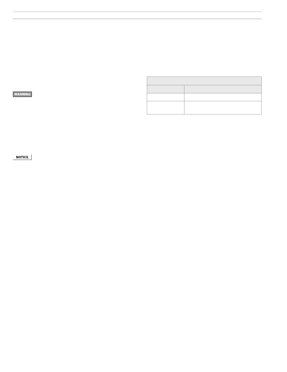
Verify power supply
1. The burner requires a 120
vac
/60
hz
/single-phase power supply, with at
least a 20-amp fuse. The current draw will be (when equipped with typical
motor and Carlin 41000 electronic ignitor) approximately:
Approximate amp draw
Motor �
1/2
HP
During ignition
Add 0.5 amps to steady current below
Steady operation
Carlin motor — 5.2
AMPS
Marathon motor — 8.4 amps
2. The 120
vac
power connections to the black and red/white wires of the
60200FR must be the same polarity
from the same power source. DO
NOT attempt to supply separate power sources. Check the power from the
appliance with a voltmeter. Verify that the supply to the black and red/white
wires are from the 120
vac
HOT side and that the power is no less than
102
vac
nor more than 132
vac
.
Wire to the burner
Connect wiring to the burner junction box as shown on the wiring diagram
supplied with the burner and any special wiring requirements shown in the
appliance instruction manual. See Figure 11 for typical wiring.
Checking burner flame signal
The 60200FR uses flame rectification to detect the flame. Because the grounded
metal surface area near the flame rod is much larger than the surface of the
flame rod, current flows through the flame more easily in one direction than the
other. This causes an AC voltage applied to the flame rod to result in a DC offset
current. (Note that, if the flame rod should touch a grounded metal part, the
current would be AC only, not DC, and the control would not sense flame.)
The 60200FR control has a 3 mm flame signal test jack (next to the terminal
block) that can be used with a flame signal meter, such as the Honeywell W136.
Or you can use a standard 3 mm stereo plug fitted with two leads (Carlin part
number 99017). Connect these leads in series with your ammeter leads to
read DC microamps.
The minimum flame signal needed to satisfy the 60200FR sensing circuit is
0.8 microamps. The control will register flame failure at any lower signal.
Code compliance
The burner/appliance installation must comply with codes listed on page 3 and
any other locally applicable codes.