BAND-IT G40269 Giant II Hand Tool User Manual
Page 3
BAND-IT-IDEX, Inc.
A Unit of IDEX Corporation
4799 Dahlia Street
Denver, CO 80216-3070 USA
P: 1-800-525-0758
F: 1-800-624-3925
Document # P36187 Rev. H
© Copyright
BAND-IT-IDEX, Inc. 2007
All rights reserved
www.BAND-IT-IDEX.com
Page 3 of 3
G40269 Giant II
Hand Tool
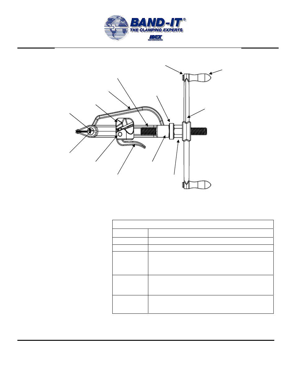
Tool Assembly
Parts List
TOOL FRAME
PIN, ECC. LEVER PIVOT
CUTTER BAR
SET SCREW
SLIDE BLOCK
CUTTER BAR HANDLE
TENSION SCREW
THRUST
BEARING
EXTERNAL RETAINING RING
TENSION HANDLE
SPIN GRIP
ECCENTRIC LEVER
TENSION NUT
1. To assist in removing threaded parts,
apply heat to soften locking compound.
2. When connecting the tension screw to
the slide block, clean threads (male and
female) of foreign matter, then apply two
drops of high strength locking compound
(Loctite 271 or equiv.) onto male threads
and connect parts together. Apply 3 oz.
of white lubricant or equiv. to tension
screw thread.
3. When connecting the set screw to the
cutter bar, clean threads (male and
female) of foreign matter, then apply one
drop of medium strength locking
compound (Loctite 242 or equiv.) onto
male thread and connect parts together.
REPAIR PARTS LIST FOR G40269
PART #
DESCRIPTION
G41387 TOOL
FRAME
G40888 THRUST
BEARING
G42487
SLIDE BLOCK ASSEMBLY
INCLUDES: SLIDE BLOCK, TENSION SCREW,
TENSION NUT, ECCENTRIC LEVER, AND LEVER
PIVOT PIN
G42087
TENSION HANDLE ASSEMBLY
INCLUDES: TENSION HANDLE, SPIN GRIP AND
EXTERNAL RETAINING RING
G42287
CUTTER BAR ASSEMBLY
INCLUDES: CUTTER BAR HANDLE, CUTTER
BAR, AND SET SCREW (ON FAR SIDE)