Install base, Install leveling kit – B&W Trailer Hitches RVK3300 User Manual
Page 3
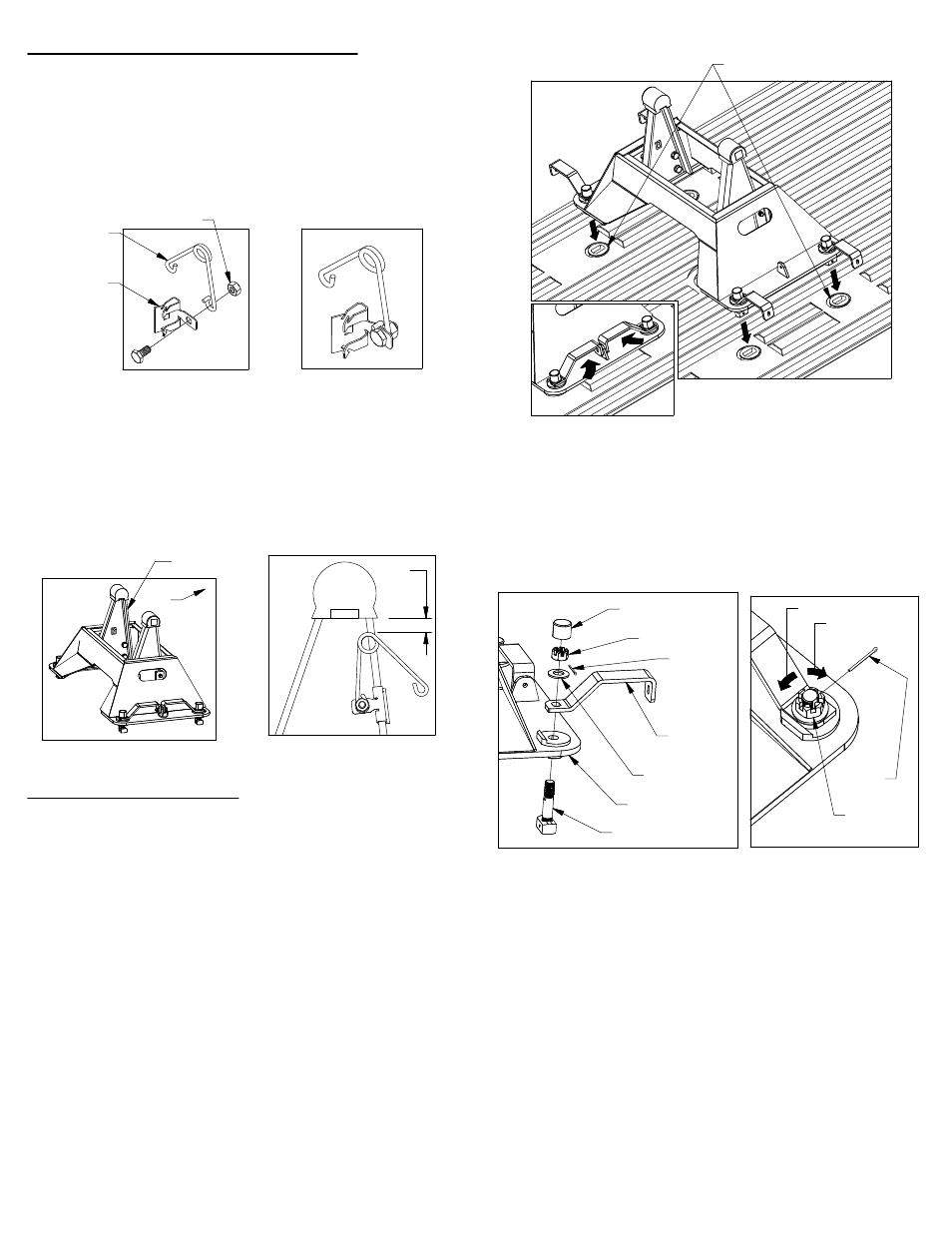
INSTALL BASE
The companion base will mount to four attachment
points in the truck bed. Remove any debris and/or
obstructions from the truck bed, this includes any
plastic caps which may be over the attachment points.
Remove the latch pins from each side of the base and
rotate the handles out, see figure C1. Place the
Companion base over the attachment points and
carefully lower it until the latch cams pass through the
floor and the base rests flat against the top of the
attachment points.
1.
Adjust the tension in the latch handle,
for parts list
and visual guide refer to figures C3 and C4.
Remove the plastic cap covering the castle nut. Next,
with a pair of needle nose pliers, un−bend and remove
the cotter pin installed at the top of the latch cam.
Next adjust the height of the castle nut.
3.
With the base firmly held down and each latch handle
closed, replace the latch pins removed in step one.
4.
Trial and error will have to be used to find the correct
latch tension for each attachment point. After the
tension is set, replace the cotter pin and re−bend the
ends. You may have to rotate the castle nut slightly to
allow the cotter pin to pass through. Replace the
plastic cap.
To tighten the latch handle (handle rotates without
any resistance) rotate the castle nut clockwise
(tighten) with a 15/16" wrench or socket.
To loosen the latch handle (handle is difficult to
rotate or cannot be closed) rotate the castle nut
counter−clockwise (loosen) with a 15/16" wrench or
socket.
INSTALL LEVELING KIT
Locate the 1/4" cap screw and nut, along with the wire
tension spring and mounting clip. Pass the 1/4" cap
screw through the mounting clip and the wire spring
as shown in figure B1. Thread the 1/4" lock nut onto
the 1/4" cap screw. Tighten the lock nut just enough
that the spring will stay in place but will still be able to
rotate around the bolt if needed, see figure B2.
1.
Locate the flange which will be closest to the truck cab
on the driver side pivot arm, see figure B3. The clip
should be placed so that when the springs coil is in the
line with the edge of the arm there will be 1/2" of
clearance between the bottom of the rubber bumper
and the top of the spring, see figure B4. Drive the clip
securely onto the flange with a hammer.
2.
Once the base is in place, turn each of the latch
handles as shown in figure C2. It is critical that the
base be drawn firmly down onto the attachment points.
You should feel some resistance while turning the
handles as the base is drawn down. If any of the
handles will not close or if they rotate freely with no
resistance, the tension on the latch handles will need
to be adjusted.
2.
FIGURE B4: Driver
side pivot arm.
FIGURE B1:
Leveling kit parts.
FIGURE B2:
Assembled leveling kit.
FIGURE C4: View of base leg.
FIGURE C1:
View of unlatched base
FIGURE C2:
View of closed latch handle
FIGURE C3: List of latch parts.
FIGURE B3: View of base.
COTTER
PIN
PLASTIC
CAP
CASTLE
NUT
SPRING
WASHER
LATCH
HANDLE
BASE LEG
LATCH CAM
LOOSEN
TIGHTEN
COTTER
PIN
CASTLE
NUT
1/2"
CAB
DRIVER SIDE
PIVOT ARM
MOUNTING
CLIP
WIRE
SPRING
1/4" LOCK NUT
ATTACHMENT POINTS