Install pivot arms – B&W Trailer Hitches RVK3500 User Manual
Page 3
Secure the base to the truck bed by first tightening
the eight 1/2" cap screws attaching the socket post
into the center of the base to 80 ft−lbs. Second,
tighten the 1/2" x 3−1/2" draw−down bolt to 60 ft−lbs.
Lock the draw down bolt in place by swiveling the
locking bracket over the draw down bolt, see figure
C2.
WARNING: Check the latch pin under the truck. Make
sure that the latch pin has passed through both sides
of the socket and that the pin is covered up inside the
socket by the socket adjuster, see figure C1.
Square the Companion base legs with the ribs of the
truck. Position the plastic pads so that they are both
in line with the rib along their entire length. Tighten
the four ¼" nuts holding the pads to the base.
Carefully lift and position the Companion base into the
GN hitch socket in the back of the truck bed. Orient
the base so that the large warning label and the
socket post are on or facing the cab side of the truck.
Re−engage the GN latch pin handle in the driver side
fender.
NOTICE: DO NOT lubricate the draw down bolt, the
torque value is for dry threads only.
WARNING: B&W also recommends that you check
the clearance between the bed side and the underside
of the front of the trailer and to allow adequate
clearance for the pitch and roll of the trailer while
towing.
Locate both pivot arms, the four ½" threaded blocks,
eight ½" cap screws, and eight ½" split lock washers.
Place the lock washers over the cap screws. Align the
flat side of the pivot arm flat against the bolt plate and
install four 1/2" cap screws through the holes on the
arm, holding the arm in place. The holes on one side
of the threaded block have a tapered edge for starting
screws. Pass the threaded blocks through the leg and
align the blocks with each set of screws and start each
screw, see figure D2. After all screws are started
through the arms, torque each bolt to 80 ft−lbs.
WARNING: B&W recommends that you check the
clearance between the truck cab and the trailer.
Compare the measurement taken from the center of
the Coupler to the cab, to the measurement taken
from the center of the king pin to the farthest forward
corner point of the trailer. These measurements will
allow you to see how much clearance you will have
between the cab and the trailer while towing and
turning.
3.
4.
5.
6.
1.
2.
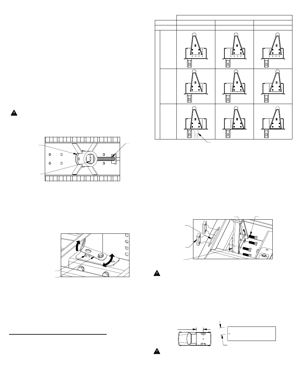
INSTALL PIVOT ARMS
Mount the pivot arms using one of the nine different
locations illustrated in Table D1. These nine locations
allow flexibility in coupler height (vertical adjustment)
and distance from the cab (horizontal adjustment).
Choose a location so that your trailer will be as level
as possible and have adequate turning clearance
while towing. See warnings after step 2.
Locate the GN latch pin handle of the Turnoverball
™
Gooseneck Hitch in the driver’s side fender well.
Retract the GN latch pin handle all the way to
disengage the pin from ball. Remove the
Turnoverball from the GN hitch receiver socket.
2.
NOTICE: Failure to "lock" the draw down bolt with the
locking bracket will allow the draw−down bolt to
loosen. Property damage may result when the base is
not properly clamped to the truckbed.
FIGURE C1: Typical view of Turnoverball
gooseneck center under bed.
FIGURE C2: View of top of base.
FIGURE D2: View looking at passenger
pivot arm mounting location.
V
E
R
T
IC
A
L
A
D
JU
S
T
M
E
N
T
HORIZONTAL ADJUSTMENT
H
IG
H
E
S
T
P
O
S
IT
IO
N
S
(1
8
1/
4"
)
LO
W
E
S
T
P
O
S
IT
IO
N
S
(1
6
1/
4"
)
M
E
D
IU
M
H
E
IG
H
T
P
O
S
IT
IO
N
S
(1
7
1/
4"
)
Kingpin
3"
behind post
Kingpin
3"
behind post
Kingpin
7"
behind post
Kingpin
1"
behind post
Kingpin
5"
behind post
Kingpin
1"
ahead of post
POSITION 2
POSITION 1
TABLE D1: Pivot arm position table
SOCKET
PIN
SOCKET
ADJUSTER
CENTER OF
COUPLER
TO CAB
KING PIN TO EDGE OF TRAILER
LOCKING BRACKET
1/2" DRAW DOWN BOLT
1/2"
THREADED
BLOCK
HOLE IN
BASE LEG
PIVOT ARM
1/2" LOCK WASHER
1/2" CAP SCREW
POSITION 2