B&W Trailer Hitches 1257R User Manual
Page 3
STEP 3 – Cross Member Installation
There are four crossmember parts included in the kit. Two channel type and two flat type. Place one of the
channel crossmembers between the top of the frame and the under side of the bed. Make sure that both
flanges of the channel are facing down and the notches at each end are toward the front of the truck. Once
the crossmember is across both frame rails rotate it down and slide forward. Next install a flat crossmem-
ber in the same manner and slide it forward. Install the other two in the same manner except with the
notches facing the rear of the truck. Slide them toward the rear as far as possible.
STEP 4 – Center Section Installation
Install 1/2” x 2” carriage bolts through the center four holes of the front crossmembers. The threaded
part of the bolts should face toward the rear of the truck with the square part of the bolts fitting into the
square holes in the crossmembers. With the latch pin on the driver’s side, lift the center section up on to
the bolts and hand tighten with flat washers, lock washers, and nuts. Now the center section and the front
crossmember can slide forward. This will allow the 4” round top of the center to be placed into the hole in
the truck bed. A lifting device as describe previously will help if available. With the top of the center section
placed through the hole in the bed, slide the rear crossmembers against the rear of the center and install
carriage bolts in the same manner as before. All bolts must be left loose at this point for sideplate instal-
lation.
STEP 5 – Side Plate Installation
Using the diagram at the right determine the driver and passenger side-
plates. Place the appropriate side plate on the inside of the frame with the
small flanges fitting between the crossmembers. The top long flange will
sit on the upper leg of the frame with the bottom long flange sitting on
the top of lower leg of the frame. With each sideplate in place insert car-
riage bolts through the square holes in the crossmembers and through the
small flanges on the sideplates. Place a flat washer, lock washer and nut
on the bolts and leave loose at this time.
Next place a 5/8” x 1-1/2” bolt with a flat
washer and frame spacer (see diagram at
right) through the oval holes in the frame.
Two will go through the bottom frame leg
using a 1/4” frame spacer and two in the
top frame leg using a 1/8” frame spacer. Af-
ter passing through the frame and sideplate
install a lock washer and nut.
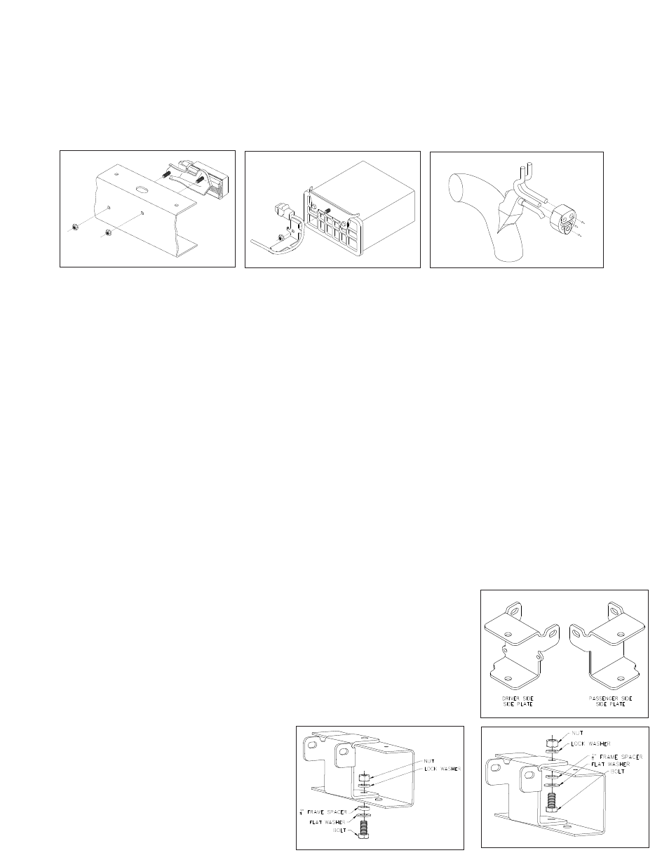
STEP 2 – Pre-Installation
Remove the two bolts holding the exhaust heat shield using a 10 mm wrench. Locate the fuel pump control
on the inside of the driver’s side frame. Using a 12 mm wrench remove the two nuts on the outside of the
frame that are holding it in place (Fig. 1). Retain the nuts to be replaced later. Next locate the fuel vapor
canister box mounted just under the front bed crossmember on the driver’s side of the truck. Remove the
nut holding the wiring bracket to the back of the box (Fig. 2). This will be relocated later. On the top of the
passenger side frame rail locate the plastic wiring bracket and remove from top of frame. Place the wiring
harness inside the frame rail. It will be held in place with the sideplate. Locate the tail pipe hanger toward
the back of the tail pipe and slide the rubber hanger off of the tubing that is welded to the pipe (Fig. 3).
(Fig. 1)
(Fig. 2)
(Fig. 3)