B&W Trailer Hitches 1197R User Manual
Page 3
Copyright 2014
B&W Custom Truck Beds, Inc.
ALL RIGHTS RESERVED
1197R - 05 01 2014
STEP 5
To install the safety chain brackets it is necessary to drill four ½” holes through the truck bed floor. Drill the
holes from beneath the truck, through the four holes furthest from the round hitch receiver tube in the cen-
ter section. Drop a U-bolt through each pair of holes from the topside of the truck bed floor. Place a spring
and lock nut on each of the four legs. Tighten the lock nuts until ¼” of thread extends through the lock nut.
STEP 7
Retract the latch pin by pulling the handle out until it stops and then rotating it slightly to the left. Place
the 2-5/16” ball in the hitch receiver. Engage the latch pin by rotating the handle slightly to the right. Be
certain the latch pin passes through the holes in the 2-5/16” ball and fully engages through both sides of
the receiver tube. Repeat this process with the 2-5/16” ball in all four positions, both upright and inverted.
Lightly lubricate the four corners of the hitch ball.
STEP 3
With the latch pin mechanism on the driver’s side of the truck, raise the center section of the hitch into posi-
tion between the crossmembers from beneath the truck. The round tube hitch receiver that protrudes from
the center section must fit through the hole in the truck bed floor. Fasten the center section to the cross-
members, as shown in Fig. A, using the six ½” x 1 ½” bolts. Start these bolts through the slots in the cross-
member using a flat washer and lock washer on each bolt. Align the assembly with frame rails and tighten.
STEP 4
Square the assembled center section and crossmembers across the frame. Install the sideplates on the out-
side of the frame rails by attaching the sideplates to the crossmembers using ½” x 1 ½” bolts, flat washer,
lock washer and nut. Do not fully tighten. Attach the sideplate to the frame utilizing 7/8” X 2 ½” bolt and the
7/16” X 1 ½” bolts provided in the mounting kit. Repeat steps on opposite side. On some frames it may be
necessary to drill the 7/16” hole. Drill one of the 3 holes at the rear of the sideplate, taking care to avoid the
fuel line, brake line and electrical wires located on the inside of the frame. With the crossmembers, center
section and sideplates installed, torque all fasteners to 90 ft. lbs., in the following sequence. (Use caution
not to damage the brake line or fuel line). First, torque the crossmembers to the center section. Second,
torque the crossmembers to the sideplates. Third, torque the sideplates to the frame rails.
LATCH
PIN
TAB
IN−LINE
DRIVER SIDE
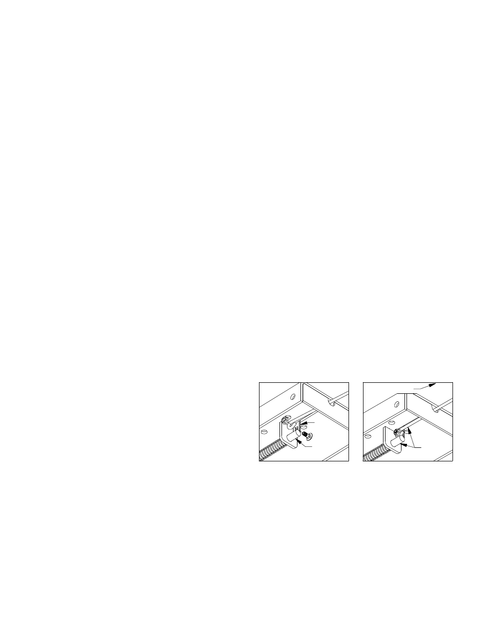
STEP 6 – INSTALL LATCH PIN RELEASE HANDLE
WARNING: LATCH PIN WILL NOT FUNCTION PROPERLY IF HANDLE IS NOT INSTALLED CORRECTLY.
Install the latch pin release handle by inserting it through the slot in the end of the center section on the
driver’s side of the truck. Align the handle eyelet with the square hole in the latch pin so the handle is in
line with the latch pin as shown. Secure the handle to the pin with the 5/16 X 3/4” carriage bolt and 5/16”
locking flange nut as shown. Note: The included 5/16” cap screw can replace the carriage bolt if wrench
access on the “cab side” of the handle is limited. Tighten the nut until it is secure. Do not over-tighten
and deform the handle eyelet.