B&W Trailer Hitches 1384 User Manual
Page 3
Mark the location of the 3−1/2" hole. Insert the hole
template into the center hole of the frame cross
member as shown in figure A6. Push the template
upward until it is flush against the bottom of the bed
floor. Make a mark on the truck bed floor through the
hole in the hole template using a pencil, marker, or
other tool. Once the center point is marked, remove
the template. Use a center punch to place an
indention in the truck bed at the center of the mark.
Using a drill and a ¼" bit, drill a pilot hole through the
bed in this location.
Cut the 3−1/2" diameter hole. From the top side of
the bed, use the pilot hole and a hole saw to create a
3−1/2" diameter hole in the truck bed floor. A saber
saw equipped with a metal cutting blade may also be
used if the 3−1/2" diameter circle is laid out on the bed
floor around the center of the pilot hole. Remove any
burrs created while cutting the hole. The size of the
round portion of the hitch that will be seen from the
truck bed was determined by the size of the hole in
the truck’s frame. The closest nominal hole size to this
feature is 3−1/2". The 3−1/2" hole will leave a gap
around the hitch structure. This gap will be filled in by
the plastic spacer block.
Most trucks have fuel lines, brake lines, electrical
wires or other vehicle systems located along the
frame rails or in the general area where B&W
Turnoverball hitches install. Carefully examine the
locations of these systems before installation.
Make certain that these are not damaged during
positioning hitch components, drilling holes, or
tightening fasteners. Damage to these systems
may result in property damage, serious injury, or
death.
Turnoverball hitch components are heavy and
may be cumbersome to handle. Failure to use
proper lifting techniques and caution when
handling these items could result in serious
injury.
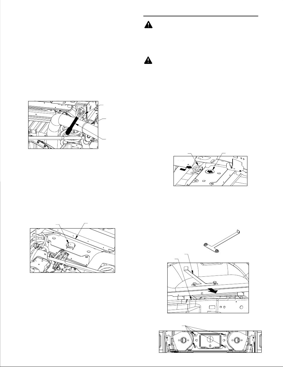
Place spacer block. Position the plastic spacer block
between the frame cross member and the bed as
shown. See figure B1. Center the hole in the spacer
block over the hole in the frame.
Install fastener handles: Place the fastener handles,
see figure B2, between the frame cross member and
the bed, see figure B3. Use the handle to guide the
welded nuts into place. Make sure that the two nuts
are directly over the holes in the frame, see figure B4.
8.
9.
1.
2.
INSTALL CENTER SECTION
Remove or modify fender liners as needed.
Some vehicles are equipped with various designs
of plastic liners inside the rear wheel wells. If the
liner in the driver side wheel well prevents access
to the opening between the bed and the frame,
just over the axle, it may need to be removed or
cut to install the handle.
Disconnect the exhaust hanger: (optional, see
secure hitch section step 3) Locate the exhaust
hanger in the rear passenger portion of the truck,
see figure A5. Disconnect the exhaust from the
hanger to provide improved mounting access to
the center section. It is recommended that a pry
bar be used to aid in disconnecting the exhaust
hanger, as shown in figure A5.
6.
7.
FIGURE A5: looking under truck bed towards cab.
FIGURE A6: looking under truck bed towards cab.
FIGURE B1: Looking up at bed from foward of the driver side tire.
FIGURE B4: Looking up at frame crossmember under truck
FIGURE B2: fastener handle.
FIGURE B3: Looking at passenger side wheel well.
EXHAUST HANGER
EXHAUST
PRY BAR
FRAME CROSSMEMBER
HOLE TEMPLATE
SPACER BLOCK
FRAME CROSSMEMBER
CENTER SECTION
MOUNTING HOLES.
TRUCK FRAME
FASTENER HANDLE