B&W Trailer Hitches 1394R User Manual
Page 3
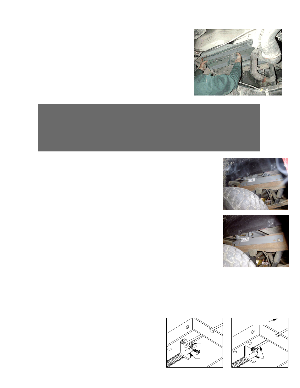
Step 4: SIDEPLATE INSTALLATION
Square the assembled center section and cross-members across the frame. Then
thread a 1 1/2” bolt with a flat and lock washer through the front flange of the side
plate into the front cross-member (bar). Next place a bolt and flat washer through
the rear side plate flange and the rear cross-member (angle iron) fasten with a flat
washer, lock washer and nut. Align one front hole and one rear hole on the sideplates
with the existing holes in the truck frame rails and fasten using 1 1/2” bolts. Install
a flat washer on the head side of the bolt and flat and lock washer on the nut side.
With the sideplates installed on both sides, torque all fasteners to 90 ft. lbs. In the
following order. First, torque the center section to the front and rear crossmembers.
Second, torque the side plates to the frame rails on both sides. Third, torque the
side plate flange to the front and r`ear crossmembers on both sides.
STEP 3: CENTER SECTION INSTALLATION
Raise the center section into position between the cross-members from beneath the truck, with the latch pin
release handle on the driver’s side. A lifting device as described on page
1 will help. The round hitch receiver that protrudes from the top of the
center section must fit through the hole in the truck bed floor. Next fasten
the center section to the front cross-member using four of the 1 1/2” bolts.
With a flat and lock washer on each bolt thread them into the threaded
hole’s in the front cross-member. Next install three 1 1/2” bolts from inside
the center section through the matching hole in the rear cross-member
(angle iron), install a flat washer, lock washer, and nut on the bolts. Do
no fully tighten at this time.
Extended Cab Short Bed Only
Before installing the sideplates, it may be necessary to remove the metal
tabs from the bed. The tabs are located on the cross-member in the front part
of the wheel opening. These tabs serve no vital purpose except at the factory at
the time of fabrication for alignment purposes.
LATCH
PIN
TAB
IN−LINE
DRIVER SIDE
STEP 5 – INSTALL LATCH PIN RELEASE HANDLE
WARNING: LATCH PIN WILL NOT FUNCTION PROPERLY IF HANDLE IS NOT INSTALLED CORRECTLY.
Install the latch pin release handle by inserting it through the slot in the end of the center section on the driver’s side
of the truck. Align the handle eyelet with the square hole in the latch pin so the handle is in line with the latch pin
as shown. Secure the handle to the pin with the 5/16 X 3/4” carriage bolt and 5/16” locking flange nut as shown.
Note: The included 5/16” cap screw can replace the carriage bolt if wrench access on the “cab side” of the handle is
limited. Tighten the nut until it is secure. Do not over-tighten and deform the handle eyelet.