Installation instructions – B&W Trailer Hitches 1050R User Manual
Page 2
INSTALLATION INSTRUCTIONS
STEP ONE
STEP TWO
From the underside of the truck, position the two crossmembers (3) and (4), across the top of the frame rails,
between the bed and frame. Start with the rear crossmember, (4) which is the solid bar. It is symmetrical,
so it doesn’t matter which end goes to the driver’s side. From behind the differential, raise the passenger
side end of the crossmember up over the frame rail and slide it through until the driver’s side can be raised
up over that side of the frame. Push the crossmember rearward until it is against the bed crossmember that
is directly above the truck’s axle. Now position the front angle iron crossmember across the frame, with the
slotted leg vertical, the horizontal leg at the top, and the slotted side toward the rear of the truck. Place the
angle parallel to the bar, about 9 inches apart, as shown in the diagram.
STEP THREE
Select the drivers side – side plate (1) (see diagram) and attach the rear slotted tab to the end of the rear
crossmember by threading a 1/2” bolt with a flat and lock washer into the threaded hole. Repeat with the
passenger side plate. With the center section (2) latch pin mechanism on the driver’s side, raise the center
section of the hitch up between the crossmembers. Guide the center section on up against the bottom of the
floor, inserting the round receiver tube through the 4” hole cut in the floor. Pull the front crossmember back
against the center section, Insert three 1/2” x 1 1/2” bolts in the front crossmember and through the front
legs of the center section. Place flat washer, lock washer and nut on the bolts. Leave these bolts loose.Thread
four 1 1/2” bolts with flat and lock washers into the rear bar from inside the center section. Now install the
bolts in the front side plate tabs.
STEP FOUR
Square the hitch across the frame and align two of the sideplate holes with existing holes in the truck frame.
Install two ½” bolts, flat washers and lock washers on each side. After all fasteners have been installed,
torque to 90 ft.-lbs. torque.
Begin by verifying and measuring the correct hole location in the truck bed floor. Measure from the back
end (tail gate end) of the truck bed floor by hooking a tape measure over the back of the the truck bed (not
including the tailgate) and marking the floor at the 44 1/4”. Center the measurement between the wheel
wells. This location is critical to the correct installation of this hitch, so measure, mark and saw carefully. If
the truck has a plastic bed liner, you may drill through both, but it is more difficult to accurately locate the
midpoint between the wheel wells, and to be sure that the bed liner does not move while sawing the hole.
Make a 4-inch hole at this location using a four inch hole saw, or by marking a 4 inch circle and cutting it out
with a sabersaw
Copyright 2014
B&W Custom Truck Beds, Inc.
ALL RIGHTS RESERVED
1050R 05 01 2014
STEP FIVE
To install the safety chain brackets, it is necessary to drill four ½” holes through
the truck bed floor. Drill the holes from beneath the truck, through the 4 holes
nearest the round hitch receiver tube in the center section. This will locate the
safety chain brackets in the valley section of the bed floor. Drop a U-bolt through
each pair of holes from the topside of the truck bed floor. Place a spring and lock
nut on each of the four legs and tighten the lock nuts until they are flush with the
bottom of the U-bolt.
STEP SEVEN
Retract the latch pin by pulling the handle out until it stops and then rotating to the lock out position. Place
the 2-5/16” ball in the hitch receiver. Engage the latch pin by rotating the handle back to center. Be certain
the latch pin passes through the holes in the 2-5/16” ball and fully engages through the hitch receiver.
LATCH
PIN
TAB
IN−LINE
DRIVER SIDE
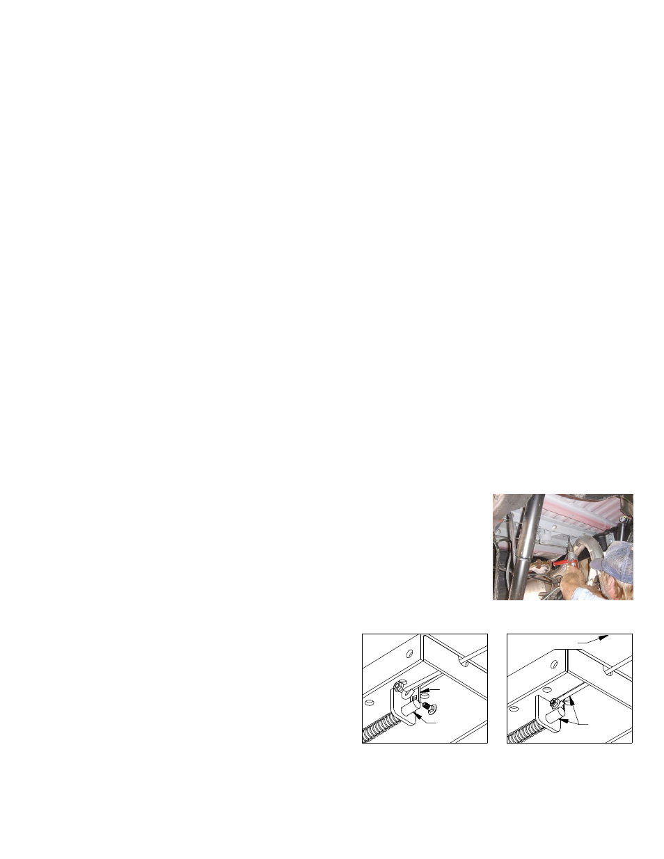
STEP SIX – INSTALL LATCH PIN RELEASE HANDLE
WARNING: LATCH PIN WILL NOT FUNCTION PROPERLY IF HANDLE IS NOT INSTALLED CORRECTLY.
Install the latch pin release handle by inserting it through
the slot in the end of the center section on the driver’s side
of the truck. Align the handle eyelet with the square hole
in the latch pin so the handle is in line with the latch pin as
shown. Secure the handle to the pin with the 5/16 X 3/4”
carriage bolt and 5/16” locking flange nut as shown. Note:
The included 5/16” cap screw can replace the carriage bolt
if wrench access on the “cab side” of the handle is limited.
Tighten the nut until it is secure. Do not over-tighten and
deform the handle eyelet.
WARNING
DO NOT invert the ball in the socket when carrying heavy loads on 2 wheel drive trucks. The ball may hit the top
of the differential. Remove the ball from the socket before loading. A plug for the socket is available from B & W.