B&W Trailer Hitches 1007R User Manual
Page 4
STEP TWELVE - INSTALL SAFETY CHAIN U-BOLTS
To install the safety chain U-bolts it is necessary to drill four 1/2” holes
through the truck bed floor. Drill the holes from beneath the truck, through
the two holes located on each side and closest to the round receiver
tube in the center section. This will locate the safety chain U-bolt in
the lowest point of the floor corrugation. Drop a U-bolt through each
pair of holes from the topside of the truck bed floor. Place a spring and
lock nut on each of the four legs. Tighten the lock nuts until flush with
the bottom of the U-bolts.
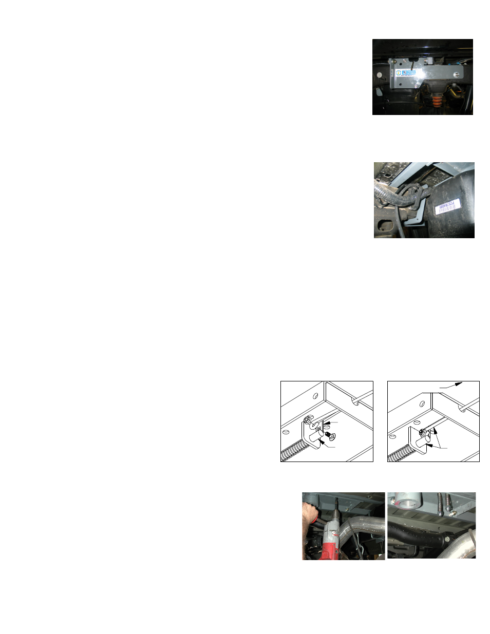
STEP THIRTEEN- REPLACE THE EXHAUST BRACKET
Re-attach the exhaust to the hanger bracket and replace spare tire if removed during the installation.
Next install the side plates. The driver’s side is shown; the longer flange goes toward the front of the truck and
the single oval hole to the rear. Place the side plate over the side plate studs that have
been install in the frame. Secure with a flat washer, lock washer, and 1/2” nut. Hand
tighten until the sideplate is against the frame and flat washer on the stud assembly.
Attach the front flange of the side plate to the front angle crossmember. Place a 1/2” by
1 1/2” bolt with a flat washer though the flange and the front angle then secure with a
lock washer and nut. Next attach the sideplate to the rear bar by placing a 1/2” x1 1/2”
bolt with a flat washer, and lock washer though the smaller side plate flange and thread-
ing it into the threaded hole in the bar.
STEP NINE - SIDE PLATE CLAMP & U-BOLT INSTALLATION
Install the sideplate clamp on the driver’s side. The sideplate clamp has two studs welded on the legs that will
pass though the highest and lowest hole in the side plate. There is a notch cut in the top inner part of the clamp
that will allow clearance for the brake line’s on the top of the frame. The small hole in
the clamp should be toward the bottom. Slide the sideplate clamp between the wiring
harness and the inside of the frame making sure the top part of the clamp goes over the
brake lines. Push the clamp outward placing the studs though the holes in the side plate.
Be careful not to damage brake lines or wire’s. The sideplate clamp will set at a diagonal
when installed correctly. Place a 1/2” lock washer and nut on the studs. The passenger
side plate will use a U-bolt in the front two holes. The U-bolt will fit around the frame
and will set vertically, not on a diagonal like the clamp. Place a lock washer & nut on
each of the threaded ends of the U-bolt once they have been installed through the side
plate holes.
STEP TEN – TIGHTEN HARDWARE
It is very important to tighten hardware in the proper sequence. First check to insure that the hitch cross-
members are spaced about the same from side to side on the frame. Then tighten the center section bolts to
80 ft. lbs. Next tighten the sideplate clamp and the u-bolt alternating slowly between the top and bottom legs
so they are equally tightened to 40 ft. lbs. tighten the bolts holding the side plates to the front and rear hitch
crossmembers to 80 ft. lbs. then tighten the rear side plate studs to 80 ft. lbs.
STEP EIGHT - INSTALL SIDE PLATES
Copyright 2014
B&W Custom Truck Beds, Inc.
ALL RIGHTS RESERVED
1007R 05 01 2014
LATCH
PIN
TAB
IN−LINE
DRIVER SIDE
STEP ELEVEN – INSTALL LATCH PIN RELEASE HANDLE
WARNING: LATCH PIN WILL NOT FUNCTION PROPERLY IF HANDLE IS NOT INSTALLED CORRECTLY.
Install the latch pin release handle by inserting it through the slot
in the end of the center section on the driver’s side of the truck.
Align the handle eyelet with the square hole in the latch pin so the
handle is in line with the latch pin as shown. Secure the handle to
the pin with the 5/16 X 3/4” carriage bolt and 5/16” locking flange
nut as shown. Note: The included 5/16” cap screw can replace the
carriage bolt if wrench access on the “cab side” of the handle is
limited. Tighten the nut until it is secure. Do not over-tighten and
deform the handle eyelet.