APG DCR-1006 user manual User Manual
Page 20
DCR-1005 and DCR-1006
Rev. A4, 10/08
20
Automation Products Group, Inc.
APG...Providing tailored solutions for measurement applications
Tel: 1/888/525-7300 • Fax: 1/435/753-7490 • www.apgsensors.com • [email protected]
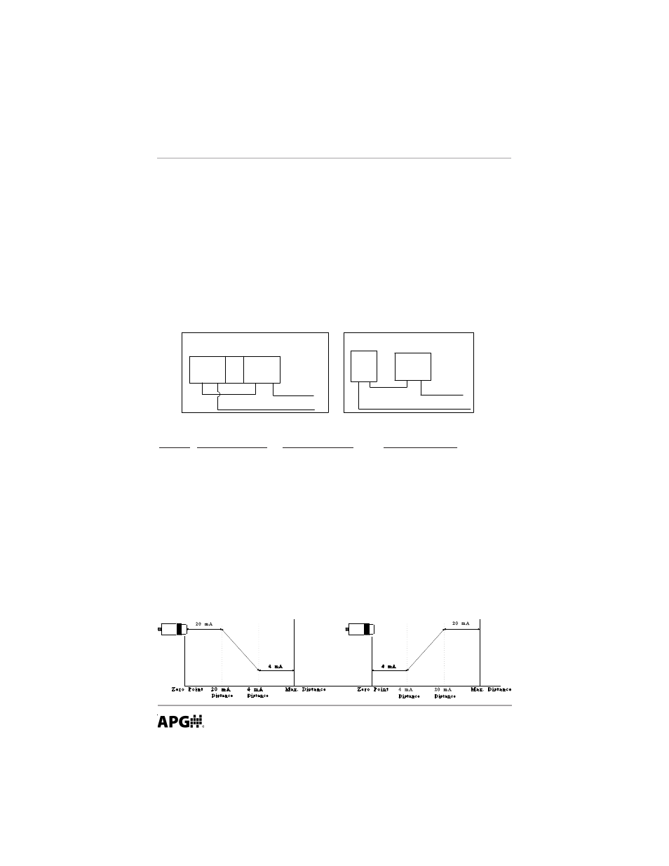
Analog
The DCR-1006 has an Isolated 4-20 mA circuitry. To set up this feature, enter
the two end points. For performing a distance to level measurement, the zero
point of distance will be at the transducer and the 4-20 limits will be
programmed in the same units as mode 1. For volumetric monitoring, the zero
point will be at the empty point of the tank and the end points must be set in
the units used in the volume measurement. Keep this in mind when referring to
the diagram below. Remember that this circuit is Loop Powered. Power must be
supplied to the 4-20 mA terminal for this feature to operate.
MODE DESCRIPTION
PARAMETERS
EXPLANATION
24
4 mA distance
Units = mode 1
Sets the minimum value
Default = 3.00 ft.
of the analog output slope
25
20 mA distance
Units = mode 1
Sets the maximum value
Default = 4.00 ft.
of the analog output slope
26
4 mA calibration
Approx. 5000
Fine tunes the minimum
current sourced on the
analog output
27
20 mA calibration
Approx. 5000
Fine tunes the maximum
current sourced on the
analog output
External
P o w e r
Source
(-) (+)
4-20(+)
4-20(-)
Isolated 4 to 20 ma output
24V
DIG
GND
4-20 ma output
Analog Ground
Current sourcing 4 to 20 ma output
Analog Ground
4-20 ma output
4-20(+)
4-20(-)