12 • ammco drum & disc brake lathes – AMMCO 4000E Drum and Disc Brake lathe User Manual
Page 14
12 • AMMCO Drum & Disc Brake Lathes
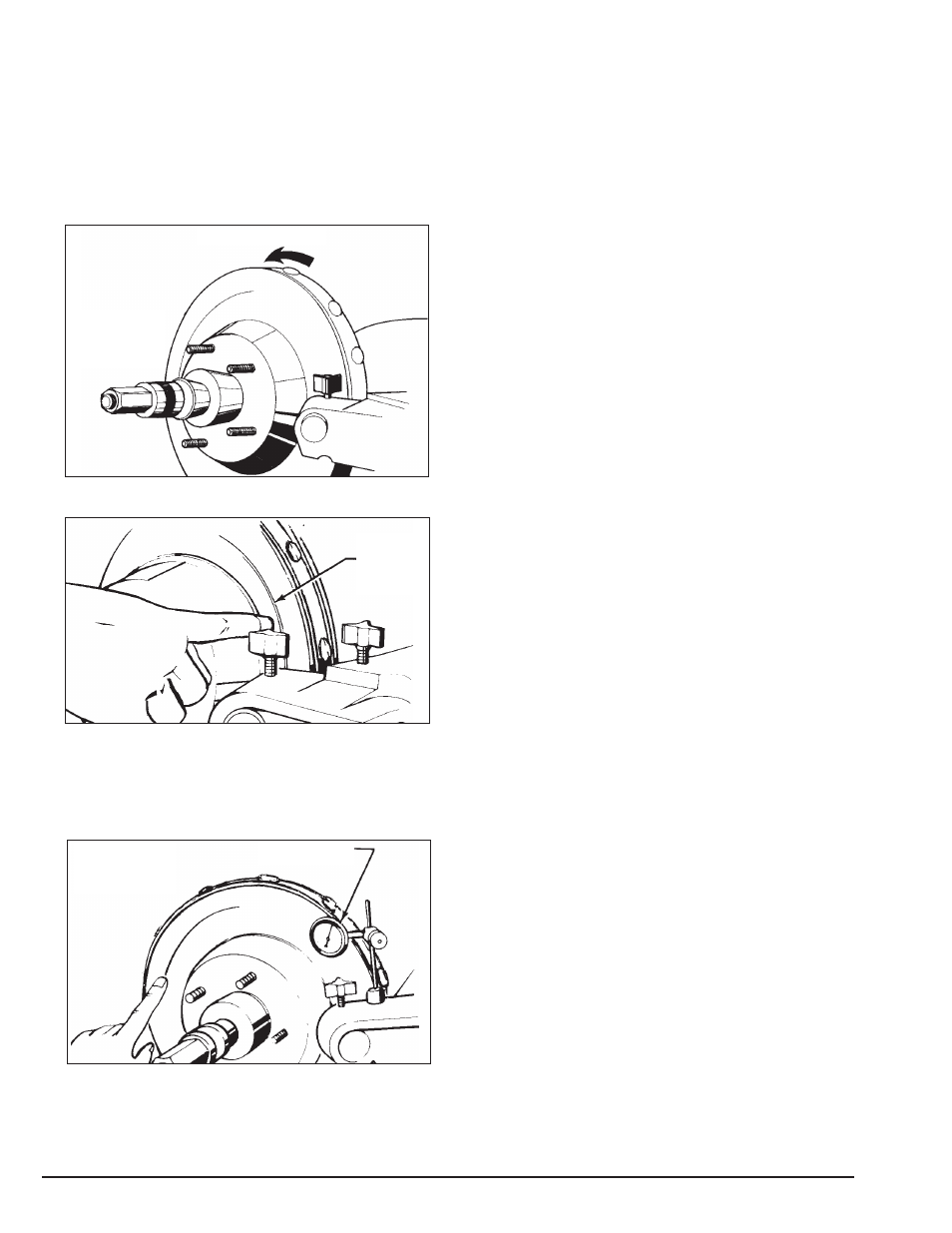
11. If you see excessive runout on the rotor:
A. Check rotor mounting by loosening the arbor
nut and turning the rotor 180° by hand on the
arbor. Make sure the inside adapter does not
rotate along with the rotor. Then retighten the
arbor nut, turn the cross feed handwheel back 1/2
turn, turn the lathe ON, and repeat step 10 to
make a second scratch cut.
Figure 13 – Rotate rotor 180°
Figure 14 – Second scratch cut
B. If the scratch cuts are side-by-side, the runout or
wobble is caused by rotor condition. A dial
indicator may be used to compare rotor runout
with manufacturer’s specifications.
Figure 15 – Using a dial indicator
C. If the scratch cuts are opposite one another
(180°), the rotor may not be properly mounted on
the arbor. Remove the rotor and examine the arbor
and all adapters for nicks, burrs, chips, dirt, or rust.
Inspect the rotor hub for loose or damaged
bearing cups. Clean, repair, remount, or replace as
necessary.
D. Recheck setting of the depth-of-cut collars which
were set to zero earlier by moving the tool bits
inward until they just contact the surfaces of the
rotor. The collars should be at zero. Reset the collars
if necessary.
12. Turn the cross feed handwheel clockwise until
the tool bits are near the rotor hub.
13. Turn the lathe ON.
14. Turn both tool bit controls to the desired depth-
of-cut and lock them in position by tightening the red
lock knobs above the tool bits.
Note: Either rough or finish cuts may be taken to
resurface a rotor. Generally, finish cuts should be
0.004” (0.10 mm) to 0.006” (0.15 mm) per side. Very
shallow cuts of less than 0.004” (0.10 mm) per side
tend to reduce tool bit life because the heat generated
during reconditioning isn’t transferred to the rotor effi-
ciently. Rough cuts may be taken from 0.006” (0.15
mm) to 0.010” (0.25 mm) per side.
15. Press the rotor start button on the control con-
sole and then engage the feed lever that is located on
the right side of the cross feed handwheel.
Note: The rotor feed rate may be changed by pressing
either the + or - button on the control console.
16. When the lathe has finished machining the rotor.
Turn the lathe off and loosen the cutting engagements.
Rotate rotor only 180°
Loosen arbor
nut, do not turn
inside adapter
Second
scratch cut
Scratch cuts
opposite each
other
Dial indicator