Allen&Heath Scepter USER GUIDE User Manual
Page 14
Audio Owner Manual
Section 2
PFL
PEAK
FRONT PANEL CONTROLS INPUT CHANNEL
11.
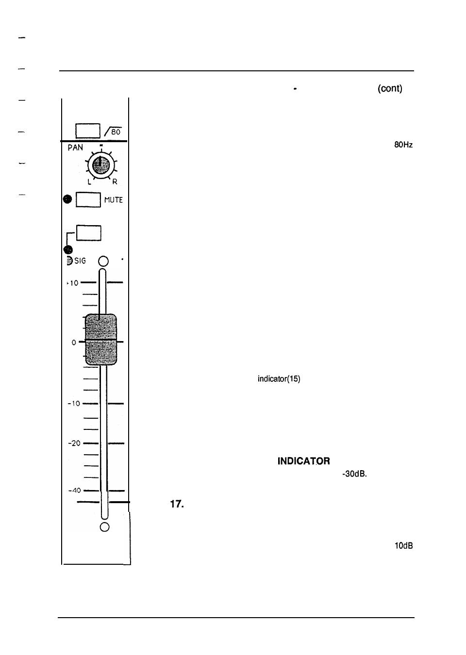
HIGH PASS FILTER SWITCH
Causes a gradual roll off in level of all frequencies below
at a rate of -12dB per octave. Useful in eliminating unwanted
low frequency sounds.
12.
PAN CONTROL
Positions input signal anywhere between the Left and Right
outputs of the stereo mix. Full counter-clockwise routes all of
the input signal to the left channel. Full clockwise routes all of
the input signal to the right channel. With this control centered,
an equal amount of signal is routed to the Left and Right
channels.
13.
MUTE SWITCH (with LED Indicator)
Cancels or mutes the channel and all of its auxiliary sends
(SEE USER OPTIONS), but does not affect PFL or peak and
signal present indicators. The mute LED illuminates when the
channel is MUTED.
14.
PFL SWITCH
Allows the operator to monitor channel levels prior to the fader,
regardless of fader level or channel mute status. Used with the
input gain control (1) and peak indicator (15) and signal present
indicator (16) to accurately set input signal levels. With PFL
selected, the peak
will come on at half intensity.
15.
PEAK INDICATOR LED (Red)
Illuminates 3dB before the onset of actual channel clipping and
is affected by the INPUT GAIN, EQ Settings, and CHANNEL
FADER settings. If any circuit is approaching overload, the LED
indicator will illuminate.
16.
SIGNAL PRESENT
(Green)
Illuminates when input signal is above
Green LED
indicator will vary in intensity with normal signal input variations.
CHANNEL FADER
Controls the level of the input channel to the Left/Right and
Mono outputs and any POST fader auxiliary sends. The fader
marking 0 is normal operating position, indicating unity gain
between input and output sections. There is an extra
boost available at the fader which is obtained by raising the
fader to its full up position.
9