AirLive SNMP-24MGB User Manual
Page 138
4. Web Management in SNMP-24MGB
131
AirLive SNMP-24MGB User’s Manual
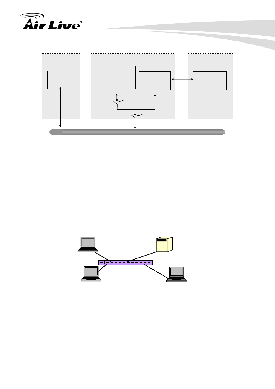
In below figure, this is the typical configuration, a single supplicant, an authenticator and an
authentication server. B and C is in the internal network, D is Authentication server running
RADIUS, switch at the central location acts Authenticator connecting to PC A and A is a PC
outside the controlled port, running Supplicant PAE. In this case, PC A wants to access the
services on device B and C, first, it must exchange the authentication message with the
authenticator on the port it connected via EAPOL packet. The authenticator transfers the
supplicant’s credentials to Authentication server for verification. If success, the
authentication server will notice the authenticator the grant. PC A, then, is allowed to
access B and C via the switch. If there are two switches directly connected together instead
of single one, for the link connecting two switches, it may have to act two port roles at the
end of the link: authenticator and supplicant, because the traffic is bi-directional.
The below figure shows the procedure of 802.1X authentication. There are steps for the
login based on 802.1X port access control management. The protocol used in the right side
is EAPOL and the left side is EAP.
1. At the initial stage, the supplicant A is unauthenticated and a port on switch acting as
an authenticator is in unauthorized state. So the access is blocked in this stage.
2. Initiating a session. Either authenticator or supplicant can initiate the message
exchange. If supplicant initiates the process, it sends EAPOL-start packet to the
Supplicant A
B
C
Authentication server
Authenticator
LAN
Authenticator
PAE
Services Offered
by Authenticator
(e.g Bridge Relay)
Authenticator’s System
Authentication
Server’s System
Authentication
Server
Supplicant
PAE
Supplicant’s
System
Uncontrolled port
Controlled port
MAC Enable
Port Authorize