Connector description, Telephone lines connection – 2N SmartGate - User Manual User Manual
Page 9
4
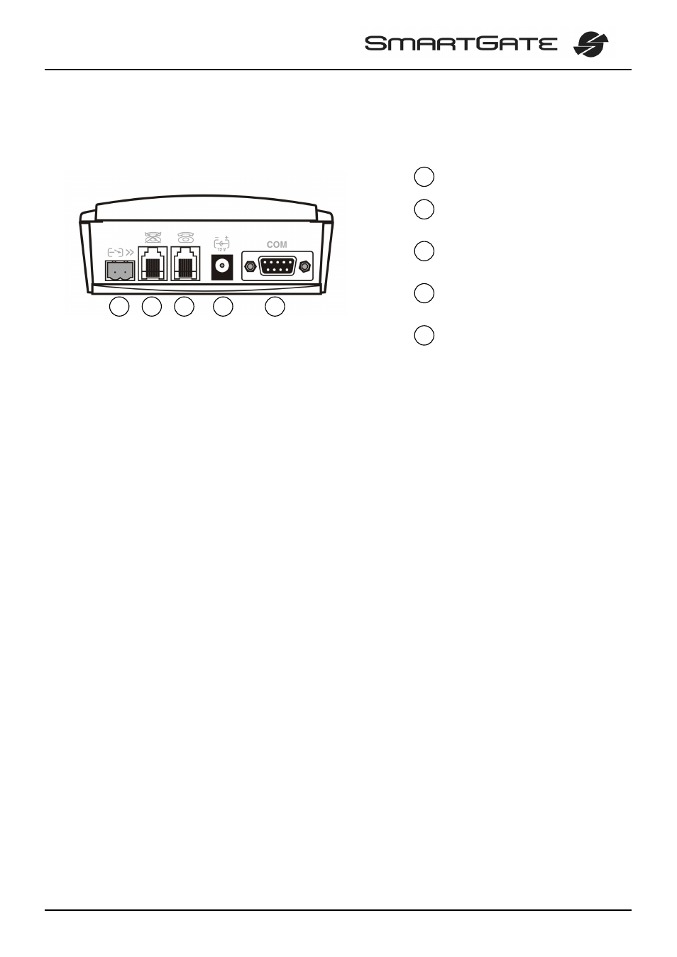
2.4. Connector description
SMS sending input
Telephone line – interface FXO
RJ 11, 6/2
Telephone line – interface FXS
RJ 11, 6/2
Power supply connector
DC Jack 5,5/2,1mm
RS232C serial line
D-Sub 9 pins
2.5. Telephone Lines Connection
2.5.1. DialThru gateway – basic connection
Phone set is normally connected to extension line of PBX. Wire up SmartGate
between phone set and PBX. Link extension line of PBX to FXO interface and phone
set to FXS interface on SmartGate.
2.5.2. Gateway for extension line of PBX
Link free extension line of your PBX to FXO interface on SmartGate. FXS interface
remains unconnected.
2.5.3. Gateway for trunk line of PBX
Link free trunk line of your PBX to FXS interface on SmartGate. Program PBX to
route all GSM calls to SmartGate. Incoming calls from GSM network will be routed to
PBX.
You can connect a standard telephone, answering machine or any other FXO-interface
terminal to SmartGate. Outgoing calls from phone will be routed to GSM network, incoming
calls from GSM will ring on the phone.
SmartGate is equipped with the FSK-based CLIP and so it is advantageous to connect a
terminal that is able to display or process the CLI. You must activate the function on
SmartGate.
2.5.4. Gateway for both, trunk and extension, lines of PBX
SmartGate is very flexible thanks to his three routing tables. You can connect trunk and
extension lines of one PBX to proper connectors on SmartGate. You can program the
complex as follows: outgoing calls from PBX will be routed through trunk line to GSM
network. Incoming calls from GSM will be routed to extension line of PBX. This
configuration is suitable for PBX’s with no capability of dial-in on trunk lines.
2
4
5
1
2
3
4
5
3
1