Location of components - platform support -4, Location of components - boom powertrack -4 – JLG 600SC_660SJC ANSI Service Manual User Manual
Page 44
SECTION 4 - BOOM & PLATFORM
4-4
– JLG Lift –
3120794
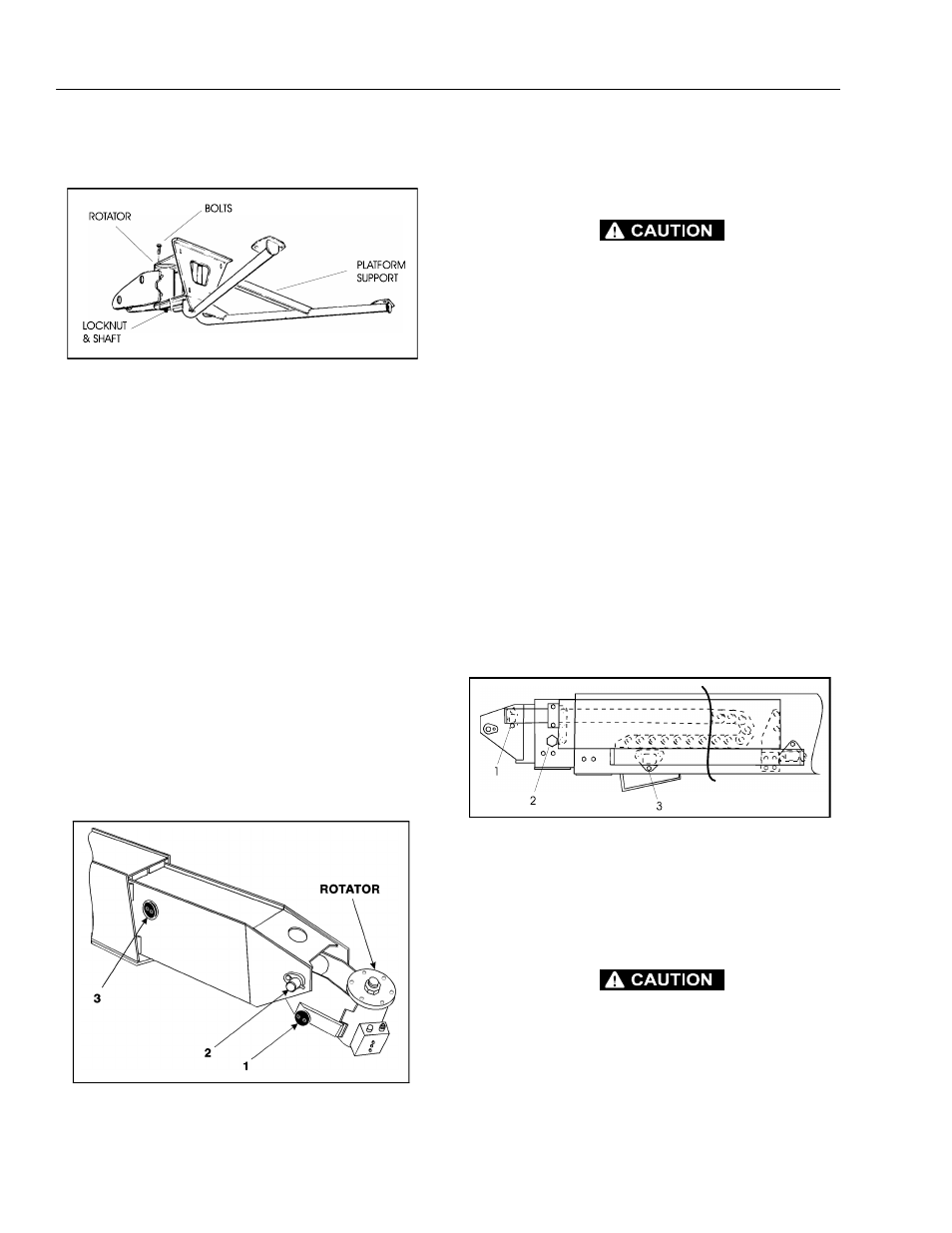
e. Using a suitable brass drift and hammer, remove
the rotator shaft, then remove the support from
the rotator.
2.
Remove the rotator and slave level cylinder from the
fly boom as follows:
a. Tag and disconnect hydraulic lines to rotator.
Use suitable container to retain any residual
hydraulic fluid. Cap hydraulic lines and ports.
b. Remove hardware from pin #1. Using a suitable
brass drift and hammer remove pin #1 from the
fly boom.
c. Supporting the rotator, remove the hardware
from pin #2. Using a suitable brass drift and
hammer, remove pin #2 from the fly boom and
remove the rotator.
d. Telescope the fly section out approximately 20
inches (50.8 cm) to gain access to the slave lev-
eling cylinder.
e. Supporting the slave, cylinder remove the hard-
ware from pin #3. Using a suitable brass drift
and hammer remove pin #3 from the fly boom.
f. Tag and disconnect hydraulic lines to the slave
leveling cylinder. Use a suitable container to
retain any residual hydraulic fluid. Cap hydraulic
lines and ports. Remove the slave cylinder.
3.
Remove the powertrack from the boom as follows:
a. Disconnect wiring harness from ground control
box.
HYDRAULIC LINES AND PORTS SHOULD BE CAPPED IMMEDI-
ATELY AFTER DISCONNECTING LINES TO AVOID ENTRY OF
CONTAMINANTS INTO SYSTEM.
b. Tag and disconnect hydraulic lines from boom
to control valve. Use a suitable container to
retain any residual hydraulic fluid. Cap hydraulic
lines and ports.
c. Disconnect the dual capacity indicator limit
switch from side of boom section.
d. Remove hydraulic lines and electrical cables
from powertrack.
e. Using a suitable lifting equipment, adequately
support powertrack weight along entire length.
f. Remove bolts #1 securing the push tube on the
fly boom section.
g. Remove bolts #2 securing the push tube on the
mid boom section.
h. With powertrack support and using all applica-
ble safety precautions, remove bolts #3 and #4
securing rail to the base boom section. Remove
powertrack from boom section.
4.
Remove boom assembly from machine as follows:
a. Using suitable lifting equipment, adequately
support boom assembly weight along entire
length.
HYDRAULIC LINES AND PORTS SHOULD BE CAPPED IMMEDI-
ATELY AFTER DISCONNECTING LINES TO AVOID ENTRY OF
CONTAMINANTS INTO SYSTEM.
b. Tag and disconnect hydraulic lines from tele-
scope cylinder. Use a suitable container to retain
any residual hydraulic fluid. Cap hydraulic lines
and ports.
Figure 4-5. Location of Components - Platform Support
Figure 4-6. Location of Components - Rotator and
Leveling Cylinder
Figure 4-7. Location of Components - Boom Powertrack