Operation checklist, Troubleshooting guidelines, Troubleshooting problems – Aerovent IM-745 User Manual
Page 7
Aerovent IM-745
7
have the capability to be “Locked Out – Tagged Out”
by the service person working on the unit. The key to
the lock is to be retained by the service person to pre-
vent the accidental powering up of the fan while the
service person is working on the fan.
Appropriate hearing protection is to be used by all
personnel in the area of the fan while it is in operation.
Due to the nature of applications where FRP fans may
be used, it is highly probable that the airstream con-
stituents should not come in contact with body parts of
the service person or their clothing. Follow all local plant
safety requirements in regards to the exposure for the
specific airstream constituents present.
Fan housings equipped with optional access doors
should never be opened while the fan is in operation.
The close proximity of the fan wheel to the access door
opening is very dangerous when operating and can
present a fatal consequence.
Fans by their nature develop a negative pressure
(suction) at their inlet while in operation. Great care must
be taken to prevent this force from causing anything that
is near the inlet to be sucked into the rotating fan wheel.
Great harm to the fan as well as to the object taken
inside the fan can occur. This can also present a fatal
consequence. The same affect can be had due to the
high velocity air stream present which will also force
objects into the fan.
Even when the fan is not in operation, sometime
there are pressure differences present which can cause
the fan wheel to “windmill”. Great care must be exer-
cised to prevent injury when working on the fan. It is
advisable to temporarily block the wheel to prevent
unexpected rotation and potential injury from occurring.
OPERATION CHECKLIST
□ Verify that proper safety precautions have been followed.
□ Electrical power must be locked off.
□ Fan Assembly is properly grounded for static dissipation
option.
Check Fan Mechanism Components:
□ Nuts, bolts, and setscrews are tight.
□ Mounting connections are properly made and tightened.
□ Bearings are properly lubricated.
□ Wheel, drives, and fan surfaces are clean and tightened.
□ Rotating assembly turns freely and does not rub.
□ Check for fan/wheel overlap per Figure 2.
□ Drives mounted on correct shaft, properly aligned,
and properly tensioned.
Check Fan Electrical Components:
□ Motor is wired for proper supply voltage.
□ Motor was properly sized for power required by the
rotating assembly.
□ Motor is properly grounded.
□ All leads are properly insulated.
Trial “Bump”:
□ Turn on power just long enough to start assembly
rotating.
□ Check rotation for agreement with rotation arrow
□ Listen for any unusual sounds.
Run Unit Up To Speed:
□ Bearing temperatures are acceptable (<200°F) after
one to two hours of operation.
□ Check for excessive levels of vibration. Filter in readings
should be 0.15 in/sec (peak) or less.
After One Week Of Operation:
□ Check all nuts, bolts, and setscrews and tighten if
necessary.
□ Readjust drive tension if necessary.
TROUBLESHOOTING GUIDELINES
Use current safety practices when investigating fan or
system performance problems. General safe practices
and performance troubleshooting guidelines can be
found in AMCA Publications 410 and 202, respectively.
Fan application and field measurement procedures can
be found in AMCA Publications 201 and 203.
Below is a list of possible areas to check when air,
sound, or operational values do not match expectations.
Most fan problems can be pinpointed to one of these
common causes.
TROUBLESHOOTING PROBLEMS
Air Capacity Problems
1. Resistance of the system is not at design rating. If
resistance is lower than expected, both airflow and
horsepower may be up. If resistance is higher than
anticipated, air volume will be down.
2. Fan speed is not at design speed.
3. Air density at the fan inlet is not at the design value.
Also check air performance measurement techniques
and procedures.
4. Devices for air modulation are closed or plugged.
Also check filters.
5. Wheel mounted improperly or is rotating in reverse.
6. Parts of the system or fan have been damaged or
need cleaning.
Noise Problems
1. Air performance is incorrect and the fan is not at the
design point of operation. Fan is being forced to
operate in an unstable flow region.
2. Bearing failure. Check bearing lubrication, alignment,
and fastener tightness.
3. Supply voltage high or inconsistent supply frequency.
Adjustable frequency controllers (VFD) can generate
motor noise.
4. Objects which are installed in a high velocity air stream
can generate noise. This includes flow sensors, turning
vanes, etc.
5. Poor fan inlet conditions.
6. Acoustic or sound measurement procedure is incorrect.
Vibration Problems
1. Misalignment of drive components. Check belts or
coupling.
2. Poor foundation or mounting structure (resonance).
3. Foreign material attached to the rotating components.
4. Damaged rotating components (bearings, shaft, fan
wheel, sheaves, coupling, seals, etc.)
5. Broken, loose, or missing setscrews, bolts, or fasteners.
6. Vibration transmitted by another source.
7. Fan is operating in stall or unstable flow region.
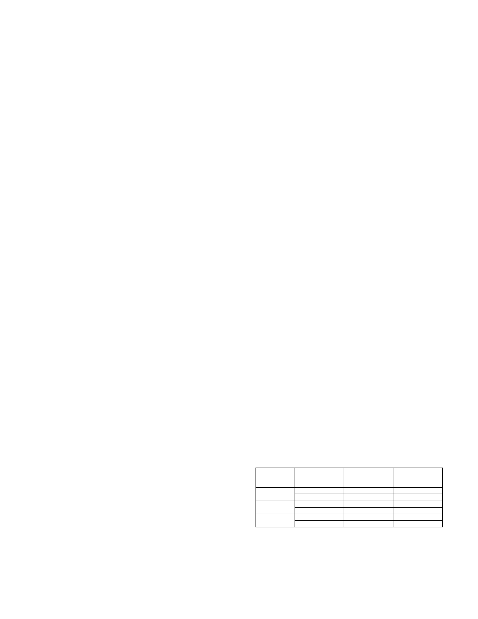
Figure 7. Vibration Guidelines
Seismic Vibration Velocity Limits for Operation In-Situ
Condition
Fan
Application
Category
Rigidly Mounted
mm/s (in./s)
Flexibly Mounted
mm/s (in./s)
Start-up
BV-3
6.4 (0.25)
8.8 (0.35)
BV-4
4.1 (0.16)
6.4 (0.25)
Alarm
BV-3
10.2 (0.40)
16.5 (0.65)
BV-4
6.4 (0.25)
10.2 (0.40)
Shutdown
BV-3
12.7 (0.50)
17.8 (0.70)
BV-4
10.2 (0.40)
15.2 (0.60)
Value shown are peak velocity, mm/s (inches/s), Filter out.
Table taken from ANSI/AMCA Standard 204-05, Table 6.3.
AMCA defines BV-3 for applications up to 400 HP; BV-4 for applica-
tions over 400 HP.