Bearing maintenance, Drive installation, Drive maintenance – Aerovent IM-745 User Manual
Page 4: Flexible coupling installation
4
Aerovent IM-745
BEARING MAINTENANCE
Proper lubrication of the fan bearings helps assure
maximum bearing life. All fans are equipped with decals
indicating relubrication intervals for normal operating condi-
tions. Figures 9, 10 and 11 illustrate the lubrication sched-
ules for ball bearings, solid pillow block spherical roller
bearings, and split pillow block spherical roller bearings,
respectively. Note that all speeds shown do not apply to
all shaft sizes in that group. Consult the factory if in doubt
of maximum speed for a particular bearing. Note that every
installation is different and the frequency of relubrication
should be adjusted accordingly.
On applications where there is high moisture or heavy
dust, the lubrication frequency may need to be doubled or
tripled to adequately protect the bearings.
Observation of the conditions of the grease expelled from
unit ball or roller bearings at the time of relubrication is
the best guide as to whether regreasing interval and
amount of grease added should be altered.
Spherical roller bearings with split pillow block housings
should be lubricated until grease purges or overheating
may result. Follow the lubrication interval and amount
noted in Figure 11. Spherical roller bearings with split pil-
low block housings should be serviced once per year.
Remove cap, clean out old grease, and replace by filling
the bottom half of the housing 1/3 full.
Greases are made with different bases. There are syn-
thetic base greases, lithium base, sodium base, poly urea
base, etc. Avoid mixing greases with different bases. They
could be incompatible and result in rapid deterioration or
breakdown of the grease. The lubrication sticker identifies
a list of acceptable lubricants. All bearings are filled with
a lithium based grease before leaving the factory. When
the fans are started, the bearings may discharge excess
grease through the seals for a short period of time. Do
not replace the initial discharge because leakage will cease
when the excess grease has worked out. Sometimes the
bearings have a tendency to run hotter during this period.
This is no reason alarm unless it lasts over 48 hours or
gets very hot (over 200°F). When relubricating, use a suf-
ficient amount of grease to purge the seals. Rotate bear-
ings by hand during relubrication.
DRIVE INSTALLATION
Mount drives as follows:
1. Slip (do not pound) proper sheave and its bushing
onto corresponding shaft (position per Figure 3).
CAUTION: placing fan sheave on motor can over
speed the wheel and cause structural failure.
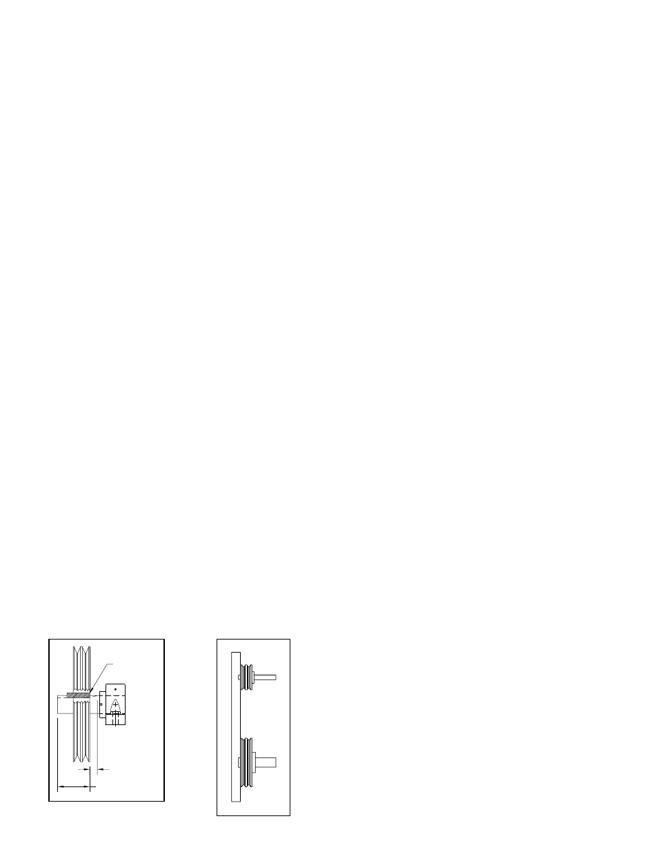
2. Align sheaves with a straightedge extended along
sheave face, just making contact in two places on
outside perimeters of both sheaves (reference Figure
4). This “four-point” alignment may also be checked
with a string tied to the shaft behind one of the
sheaves. The string is then pulled taut over the faces
of the sheaves to check the alignment at the four
points at the outside perimeters. Each sheave should
be rotated about one-half revolution during the check
to look for excessive runout or a bent shaft.
3. Install and tighten the belts. Run the drive for a few
minutes to seat the belts. When tightening the belts,
slide the motor in to slip the belts on. Do not use
a pry bar, as this may damage the belt cords.
Tighten the belts to the proper tension. Ideal tension
is just enough tension so that the belts do not slip
under peak load. Many drives are provided with ten-
sioning data which identifies the load to apply at the
center of the span and the allowable deflection from
this force. This may be checked visually (look for a
slight bow on slack side), or listen for a squeal on
startup, indicating that the belts are too loose.
Recheck sheave alignment.
4. After initial installation of belts, recheck belt tension
again after a few days and adjust tension as needed.
(New belts require a break-in period of operation.)
DRIVE MAINTENANCE
V-belt drives need periodic inspection, re-tensioning,
and occasional belt replacement. Look for dirt buildup,
burrs, or obstructions when inspecting drives. These can
cause premature belt or drive replacement. If burrs are
found, use fine emery cloth or a stone to remove the
burr. Be careful that dust does not enter the bearings.
Check the sheaves for wear. Excessive slippage of
belts on the sheaves can cause wear and vibration.
Replace worn sheaves with new ones. Carefully align
sheaves to avoid premature sheave failure.
Observe belts for signs of wear. If fraying or other
wear is observed to be mostly on one side of the belts,
the drives may be misaligned. Reinstall the drives accord-
ing to instructions given for “Drive Installation”. Never use
belt dressing on any belts. Make sure the sheaves and
belts are free from all forms of lubricants.
Always replace the entire set of v-belts and never mix
used belts with new belts. Follow instructions given for
“Drive Installation”.
FLEXIBLE COUPLING INSTALLATION
These instructions are general for the installation of
several types of flexible couplings and should not be used
as a substitute for more specific manufacturer’s instruc-
tions. The coupling manufacturer’s installation data is avail-
able and will give specific dimensions for alignment limits,
lubricants, etc. Refer to Item 7 in “Fan Installation” section
for alignment requirements.
Before preparing to mount the coupling, make sure that
all bearings, shaft seal, or other shaft mounted components
have been installed on the shaft.
When mounting and keying the interference fit coupling
halves to the shaft, follow supplied instructions for heating
and shrink fitting. Set the coupling halves for the normal
gap specified by the manufacturer. Coupling gap is illus-
trated in Figure 5.
The two types of misalignment are illustrated in Figure
5. Typically angular alignment is checked with feeler gages
between the hub faces. When angular alignment has been
adjusted to within manufacturer’s specification by shim-
ming, if necessary, then parallel alignment can be checked
with a straightedge and feeler gages on the hub halves’
O.D. When shimming has brought parallel alignment within
specification, angular alignment and gap should again be
checked, and adjustments made if necessary. A dial indica-
SHEAVE LINED
UP WITH END
OF KEYWAY
RUN OUT
RUN OUT OF
KEYWAY
KEYWAY LENGTH
Figure 4.
Sheave Alignment
Figure 3.
Sheave Position