General motor maintenance, Frp maintenance, Wheel and shaft maintenance – Aerovent IM-745 User Manual
Page 5
Aerovent IM-745
5
tor or laser alignment method may be used to more
accurately take the measurements described above.
Special adjustments may need to be made for couplings
used with some equipment. As an example, when cou-
plings are used with motors which have sleeve bearings,
the coupling may require provisions for limiting end float.
Larger drives may grow vertically in operation (due to
thermal expansion) requiring the driver side to be set
slightly low when at ambient temperature. Refer to spe-
cific instruction manuals or assembly drawings.
Thoroughly clean the coupling halves after completion
of alignment. Reassemble the coupling and tighten cover
bolts, washers, and nuts. Lubricate per manufacturer’s
recommendations.
GENERAL MOTOR MAINTENANCE
The three basic rules of motor maintenance are keep
the motor clean, keep the motor dry, and keep the motor
properly lubricated.
Keeping the motor and its windings clean is important
because dirt and dust serve as thermal insulation. Heat
normally dissipated by the motor is trapped causing over-
heating and/or premature failure. Blow dust and dirt out of
windings and off the motor periodically. Use a clean and
dry low pressure (50 psig) airstream so that winding dam-
age does not occur. Keep the area surrounding the motor
open so that air can circulate through the motor cooling
fan.
Motors should be kept dry to avoid electrical short
circuits. Motors kept in storage for long periods of time can
have moisture condense on the windings. Be certain the
motor windings are dry before energizing the motor.
Lubrication requirements are normally attached to the
motor. Do not overlubricate. Motor lubricants are often not
the same as the fan bearing lubricant. Some smaller motors
are lubricated for life. Motor bearing lubrication, if required,
must follow a rigorous schedule. Motors less than 10 hp
running about eight hours a day in a clean environment
should be lubricated once every five years; motors 15 to
50 hp, every three years; and motors 60 to 150 hp,
yearly. For motors in a dusty or dirty environment or run-
ning 24 hours a day, divide the service interval by two. If
the environment is very dirty or has a high ambient tem-
perature, then divide the service interval by four.
Motors controlled by variable frequency drives (VFD)
should be wired in accordance with the VFD manufacturer’s
instructions. The motor must be grounded to earth and
proper shielded cabling must be used. Motor shaft ground-
ing rings should be considered to minimize shaft voltage
from arcing through the motor bearings.
FRP MAINTENANCE
Corrosion Resistance – The type of reinforcement fiber
used in making the laminate structure will influence its
weight, strength, and also the wheel maximum safe speed.
The resin selected will influence the corrosion resistance of
the laminate and hence the product durability. The Aerovent
standard resin used for manufacturing wheel components
is the epoxy vinyl ester product Derakane 510A40 from
Ashland. The Aerovent standard resin used for manufactur-
ing housing components is the polyester product Hetron
92FR from Ashland with the option of using Derakane
510A40. Both products (without addition of antimony triox-
ide) have a flame spread rating less than 25 as tunnel
tested per ASTM E84.
See the “Corrosive Atmosphere Guide” that is located
within Aerovent Catalog 745 for suggested resin to use in
various corrosive environments. Final selection of the resin
should always be based upon customer’s experience and/
or testing conducted with desired fume concentration and
temperature. Additional corrosion resistance information is
available from Ashland at ashland.com.
Perform periodic visual inspection of the FRP laminate
to determine there is no adverse deterioration occurring
which will compromise the product’s structural integrity.
Periodic cleaning can prolong product life and should be
investigated.
Abrasion Resistance – Fans constructed of FRP materials
are intended for clean air service with humidity less than
100% or for air laden with corrosive fumes. FRP laminate
is inherently “softer” than carbon steel and stainless steel.
FRP products should not be used to convey air which
contains particulate or water (liquid or fog). Severe erosion
can occur if these items are present in the airstream. The
resin rich outer surface is subject to wear and if this layer
is compromised, the corrosive fumes can then attack the
reinforcement fiber. The combination of corrosion and abra-
sion can quickly lead to product failure.
Perform periodic visual inspection of the FRP laminate
to determine there is no adverse deterioration occurring
which will compromise the product’s structural integrity.
Weather Resistance – FRP products installed outdoor with-
out adequate protection are subject to damage from local
weather conditions. This can include impact damage result-
ing from hail or windblown objects, surface chalking or
discoloration from ultraviolet light exposure, and reduced
strength due to temperature effects resulting from high
ambient temperature and solar radiation combined with high
internal air temperature.
WHEEL and SHAFT MAINTENANCE
Periodically inspect the fan shaft and FRP wheel for
buildup, corrosion, and signs of excess stress or fatigue.
Dust or chemical deposits will usually build up on
the wheel evenly and they present no problem to per-
formance or operation until they become thick enough
to break away in crust-like pieces. When this happens,
the wheel may be thrown out of balance and the result-
ing vibration could be serious. When removing this
crustaceous accumulations, care should be taken not to
clean the fan wheel with sharp objects which might
damage the laminated surface and reduce its corrosion
resistance. Replace the wheel and shaft sub-assembly if
it shows signs of excessive wear or damage to the
laminate.
The fan wheel and shaft sub-assembly is factory bal-
anced and then the entire fan assembly is test run to
assure vibration levels are within tolerance. It is not
uncommon for the fan wheel to require some trim bal-
ancing after installation or after some period of time in
operation. Addition of FRP weights to the backplate or
frontplate can be made to bring the vibration levels back
within specification.
Check the interface between the shaft sleeve and the
wheel backplate. This joint is critical to prevent infiltra-
tion of corrosive fluids to the shaft and hub. Replace
the sub-assembly if needed.
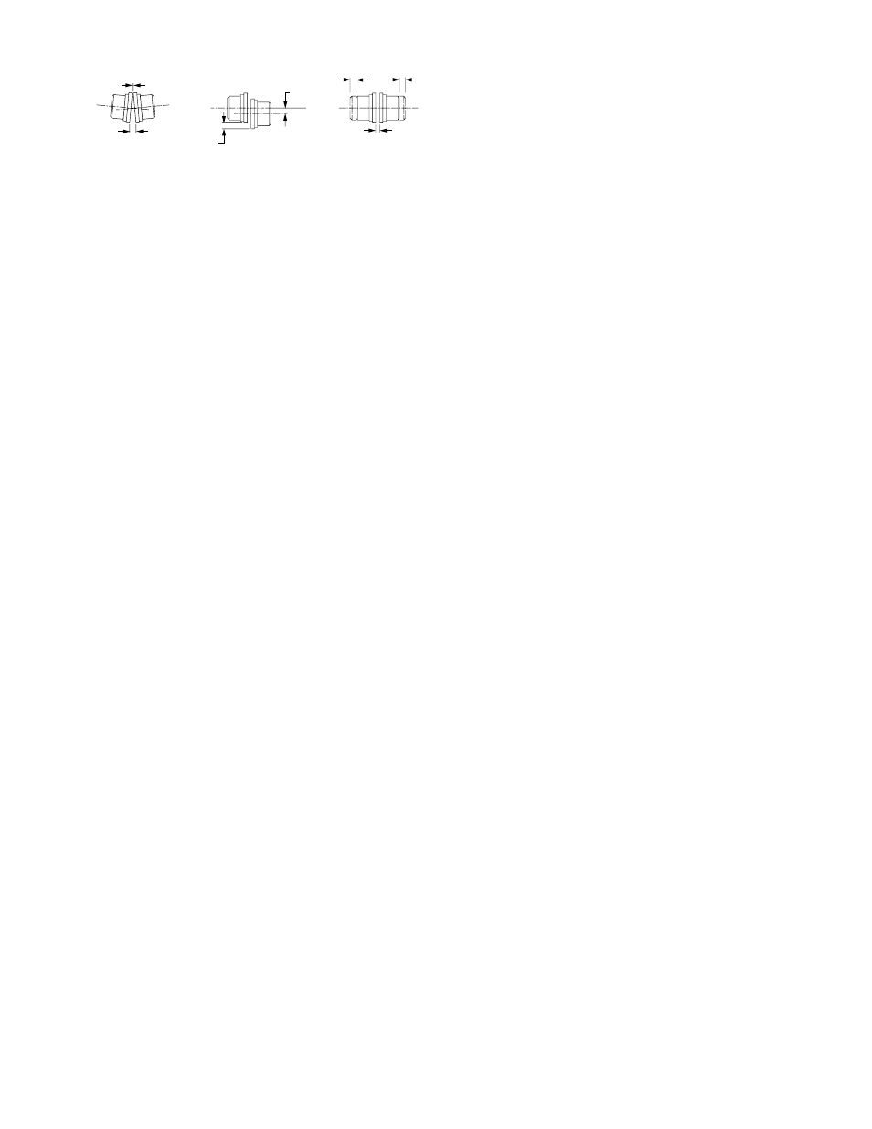
Figure 5. Coupling Installation
Y
X
P
P
F
F
GAP
ANGULAR
PARALLEL
GAP AND
MISALIGNMENT
MISALIGNMENT
END FLOAT
X-Y = ANGULAR MISALIGNMENT
P = PARALLEL OFFSET (MISALIGNMENT)
F = END FLOAT