Fan installation, Bearing installation – Aerovent IM-745 User Manual
Page 3
Aerovent IM-745
3
motor speed. This is especial true if the structure supports
more than one fan.
Fan inlet and outlet ducting should have independent
support. Do not use the fan to support ducting as the fan
housing or pedestal may become distorted or cracked. Flex
connectors at the fan inlet and discharge will isolate the
duct loads from the fan plus eliminate transmission of vibra-
tion. Use stainless steel fasteners with large washers under
the head and nut to increase the load bearing area. Do not
tighten the fasteners to the point of crushing the flange.
FAN INSTALLATION
Follow proper handling instructions as given earlier.
1. Move the fan to the final mounting position.
2. Remove skid, crates, and packing materials carefully.
3. If vibration isolation is to be used, place isolation base
on mounting bolts. Line up holes in fan base with
bolts.
4. Place the fan on mounting structure. Carefully level
the unit (checking the level on the fan shaft) on the
foundation and shim as necessary using stainless
steel shims on both sides of each anchor bolt. Be
careful not to force the fan to the mounting structure/
foundation. This may cause the bearings to become
misaligned or pinched, which can cause vibration and
premature failure.
5. Check the alignment of the bearings. Shim or reposi-
tion the bearings if necessary.
6. Check face alignment of sheaves on belt driven units
(reference Figure 4). Check tension of belts to see if
it is sufficient. Sheaves on belt driven fans are often
provided with taperlock bushings. When tightening
bushing bolts, proceed in a progressive manner to
avoid cocking the tapered surfaces between the bush-
ing and the sheave.
7. Check alignment of factory mounted couplings, as
they are subject to misalignment during shipping and
installation. Realign to within 0.002" offset and paral-
lel. Allow for thermal growth of the motor by setting
the motor 0.001" low for each inch of shaft up to
0.005". NOTE: Grid-type and gear-type couplings
require lubrication.
8. Check the tightness of the foundation bolts, motor
bolts, sheaves, and bearings. Make sure there is no
rubbing or binding and that the wheel-inlet cone
clearances are correct.
9. Check that bearings are fully lubricated. For spherical
roller bearings with split pillow block housings, the
bottom half of the housing should be 1/3 full of
grease. For oil lube bearings, the oil level should
submerge the bottom-most roller halfway.
10. Install any accessories that were shipped loose from
the factory.
11. Grouting is the final installation step. Check all stain-
less steel shims before grouting to make sure the fan
is resting evenly on all points with anchor bolts
secured to hold the shims. Use shims with sufficient
space allowed for working the grout. The concrete
foundation should be clean and well moistened before
pouring grout. Use a commercial grade non-shrinking
grout and be especially sure when pouring grout that
the anchor bolt sleeves are filled. Refer to Figure 8
for a detail of a proper foundation, grout allowance,
and anchor bolt sleeve.
BEARING INSTALLATION
The following section gives some general instructions
on bearing installation. When bearings are field installed,
the specific installation manual for the bearings should be
followed carefully. Always make sure to check the fan
assembly drawing or instructions for location of the non-
expansion and expansion bearings. The position of these
bearings cannot be interchanged.
Spherical Roller Bearings with Split Pillow Block
Housing
1. The bearings should be disassembled, taking care not
to interchange parts between bearings. Parts of one
bearing are generally not interchangeable with parts
from another bearing.
2. The lower bearing housing should be bolted loosely
to the pedestal and seals, bearing, and adapter sleeve
assembly should be placed loosely on the shaft.
3. The rotor assembly with the seals and bearings
should next be positioned over the housing and care-
fully placed into the lower housing.
4. The thrust locking ring should be installed in the bear-
ing closest to the drive sheave or coupling unless
otherwise noted in the drawing.
5. When installing adapter sleeves, tighten for reduction
in clearance per manufacturer’s instructions.
6. Bend down a tab on the lockwasher after finishing
adjustment.
7. Grease or oil according to manufacturer’s instructions.
8. Install the bearing housing cap and cap bolts. Tighten
bearing housing cap bolts and bearing mounting
bolts. Torque to bearing manufacturer’s instructions.
Solid Pillow Block
1. Slide shaft in bearing bore to proper location. Note:
Shaft should slide easily if self-aligning feature of the
shaft is within its limits. Sling the rotor assembly into
place and loosely bolt the bearings in place.
2. When bearings are in place, torque the base bolts
using values from Table 1, and tighten the collar
setscrews to manufacturer’s specification.
3. Grease the bearings per manufacturer’s instructions.
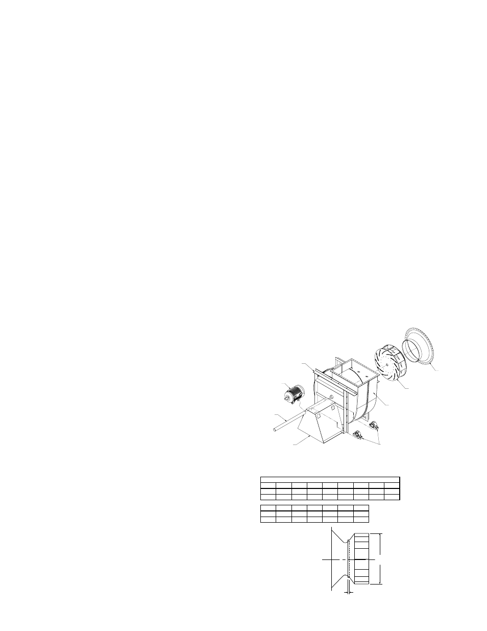
HOUSING
SUPPORT STAND
(HOUSING FRAME)
WHEEL / IMPELLER
INLET FUNNEL
PEDESTAL
SHAFT
MOTOR
BEARINGS
Figure 1.
Figure 2. Wheel Placement
A
DIA
B
BCSF Wheel Placement
Size
165
182
200
222
245
270
300
330
A
16.50 18.25 20.00 22.25 24.50 27.00 30.00 33.00
B
0.44
0.56
0.63
0.69
0.75
0.88
0.97
1.06
Size
365
402
445
490
542
600
A
36.50 40.25 44.50 49.00 54.25 60.00
B
0.94
1.03
1.13
1.25
1.38
1.56