Danger – Snorkel AB60J CE User Manual
Page 34
Chapter 7 – Prestart Inspection
30
AB60J – 0182099EE
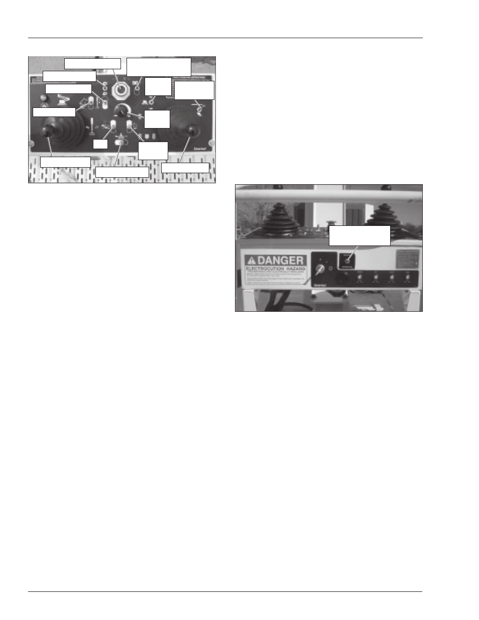
Figure 7.19 – Upper Control Panel Top
4. Turn the master start switch on the front of the up-
per control panel to start until the engine starts, then
release it.
5. Let the engine warm to operating temperature.
A
Danger
Pinch points may exist between moving compo-
nents. Death or serious injury will result from be-
coming trapped between components, buildings,
structures, or other obstacles. Make sure all person-
nel stand clear of the aerial platform while perform-
ing the prestart inspection.
6. Place the drive/boom selector switch in the boom
position.
7. Test the platform foot switch by moving a boom func-
tion switch without stepping on the foot switch. If
movement occurs the interlock is not functioning
properly. Do not operate the machine until the prob-
lem is corrected.
8. Test the operation of each control in both directions
from the upper controls.
9. The drive range switch and maximum travel speeds
are interlocked through a limit switch on the turn-
table that senses the main boom position. When
the main boom is raised to just below horizontal the
machine should travel in low speed only. To oper-
ate in high speed the booms must be stowed.
Emergency Stop
Push the emergency stop button in to turn off the en-
gine. The upper control functions should not operate with
the emergency stop in this position.
Emergency Power
Pull the emergency stop button up and place the anti-
restart master switch in the on position.
Hold the engine/emergency power switch in the emer-
gency power position and step on the platform foot switch
to operate the aerial platform from the upper controls
using the emergency power system.
Horn
Press the horn button to ensure that it sounds to warn
personnel in the area.
Electrical Power Outlet
With the engine running, place the machine/generator
control (refer to Figure 7.20) in the generator position to
provide electrical power to the outlet at the platform and
to the outlet on the end of the generator housing.
Figure 7.20 – Upper Control Panel Front
Plug an electrical tool into the receptacle at the platform
and at the generator and try to operate the tool to verify
proper operation of the outlet.
Drive Motion Alarm
The machine may be equipped with an optional drive
motion alarm. Drive in both the forward and reverse di-
rections to ensure that the alarm sounds to warn per-
sonnel in the area that the aerial platform is in motion.
Driving and Work Lights
The machine may be equipped with driving lights and/
or platform working lights. Turn the engine on and use
the switch on the back of each light to momentarily turn
it on to see that it works.
Platform Control Cover
The machine may be equipped with an optional plat-
form control cover. Inspect the cover to ensure it fits
properly over the control panel.
Tow Kit
The machine may be equipped with an optional tow kit.
Inspect the tow bar and steering arm to verify the com-
ponents are present and in working condition.
Engine Throttle
Platform
Level
Engine/Emergency
Power
Drive
Range
Speed
Knob
Emergency Stop
Boom Joystick
Platform Rotate
Drive/Boom
Selector
Drive Joystick
Boom Extend
Riser Boom
Jib
Machine/
Generator Switch