Danger, Caution – Snorkel AB60J CE User Manual
Page 29
Chapter 7 – Prestart Inspection
AB60J – 0182099EE
25
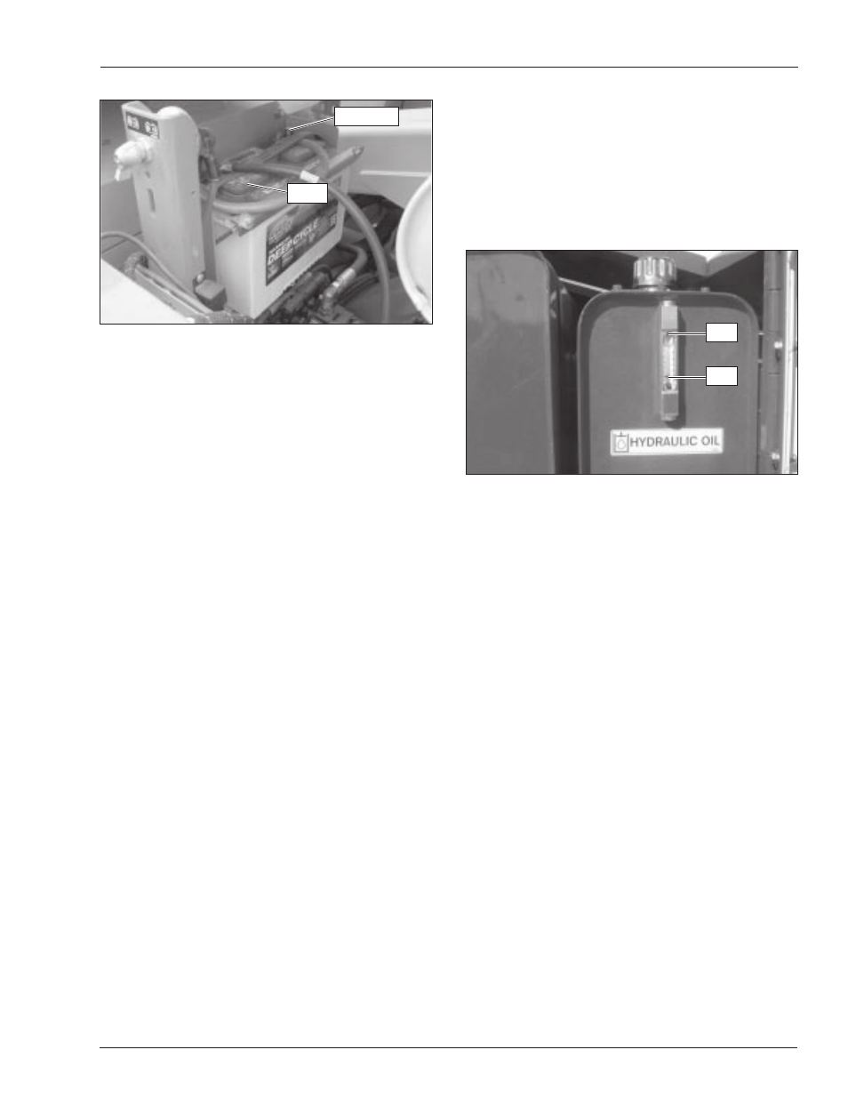
Figure 7.6 – Emergency Power Battery
Include the emergency power battery when inspecting
and servicing the electrical system.
Battery Fluid Level
Remove the caps from each battery (refer to Figure 7.6).
Visually check the battery fluid level. If the level is not
within 6 mm (
1
/
4
″) of the bottom of the filler neck inside
each hole, add distilled water.
Replace the caps on the batteries. The caps must be in
place and tight during machine operation.
Battery Terminals
Check the top of the batteries, the terminals, and cable
ends (refer to Figure 7.6). They should be clean and
free of corrosion. Clean the top of the batteries if neces-
sary.
Clean the terminals and cable ends with a wire brush or
terminal cleaning tool. All cable ends must be securely
fastened to the terminals.
Cables and Wiring Harness
Inspect all cables and wiring for wear and/or physical
damage such as loose connections, broken wires, and
frayed insulation. Check the wiring in areas where a
change in routing direction may cause them to become
pinched. Make sure the cables and wires are properly
routed to avoid sharp edges, pinching, and scuffing.
Hydraulic System
Hydraulic power is supplied from an engine driven vari-
able displacement piston pump.
A
Danger
Hydraulic fluid escaping under pressure can have
enough force to inject fluid into the flesh. Serious
infection or reaction will result if medical treatment
is not given immediately. In case of injury by escap-
ing hydraulic fluid, seek medical attention at once.
The hydraulic reservoir is behind the door on the left
side of the turntable. The pump is mounted on the en-
gine.
Fluid Level
Check the hydraulic reservoir fluid level with the aerial
platform stowed on a level surface. The fluid level must
be between the full and add marks as viewed on the
sight glass (refer to Figure 7.7).
Figure 7.7 – Fluid Level Indicator
A
Caution
Not all hydraulic fluid is suitable to use in the hy-
draulic system. Some have poor lubricating charac-
teristics and can increase component wear. Only use
hydraulic fluid as recommended.
If necessary, remove the filler cap and add fluid of the
proper type. Refer to Chapter 2 for the proper type and
grade of hydraulic fluid to use. The need to regularly
add fluid indicates a leak that should be corrected.
The sight glass on the reservoir has an internal ther-
mometer to measure the fluid temperature. The tem-
perature should be less than 93°C (200°F).
Fluid Filter
Checking the condition of the hydraulic fluid filter is part
of the machine maintenance schedule and should not
be performed by the operator.
Hoses, Tubes, and Fittings
Inspect all hydraulic hoses, tubes, and fittings for wear,
leakage, or damage (refer to Figure 7.8). Make sure the
hoses are properly routed to avoid sharp edges, kink-
ing, and scuffing. Inspect the tubes for dents or other
damage that may restrict fluid flow. Make sure all hoses
and tubes are held firmly in their support brackets.
Full
Terminals
Caps
Add