Snorkel AB46JE User Manual
Page 44
Chapter 9 – Operation
40
AB46JE – 0260072
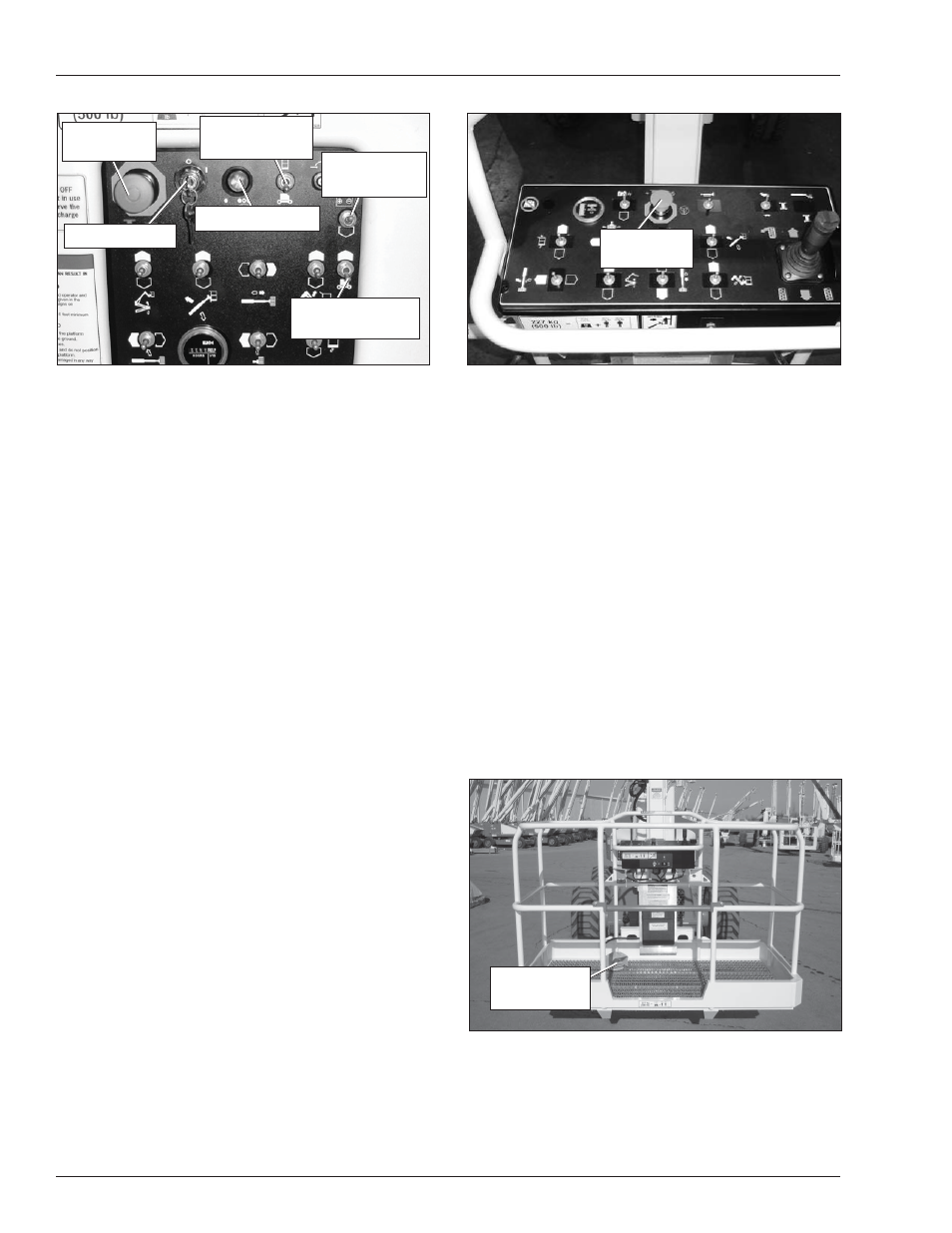
Figure 9.2 – Upper Controls
5. Step down on the platform foot switch.
6. Visually check to make sure the drive fault light is lit
at the lower controls (refer to Figure 9.1).
If the drive fault light is not lit or fl ashing, repeat
the steps 1 through 5 to ensure the controls are
set up properly.
After ensuring the controls are set up properly
and the drive fault light is not lit or fl ashing, re-
move the aerial platform from service until quali-
fi ed maintenance personnel can make repairs.
Boom Operation
Use the following procedure to operate the turntable,
boom, or platform functions.
1. Step down on the platform foot switch (refer to Figure
9.3). The platform foot switch must be held down to
operate the upper controls.
Figure 9.3 – Platform Foot Switch
2. Hold the appropriate control in the desired direction.
Always look in the direction of movement.
3. To stop movement release the control to its neutral
position or release the foot switch.
•
•
Emergency
Stop Button
Emergency
Stop Button
Platform Foot
Switch
Platform Foot
Switch
Figure 9.1 – Lower Controls
2. Insert the key into the start switch and turn the switch
to the on position.
3. Hold the ground operation switch upward while
operating the boom and turntable control toggle
switches.
4. Hold the appropriate toggle switch in the desired
direction.
5. Release the function toggle switch to stop move-
ment.
6. Release the ground operation switch to the off posi-
tion when no functions are being operated.
Upper Controls
The upper controls may be used for driving the aerial
platform and positioning the booms and platform while
on the job.
Use the following procedure to operate machine functions
using the upper controls.
1. At the lower controls, place the emergency stop
button and start switch in the on position. Place the
controls switch in the platform position.
2. Enter the platform and securely close the gate.
3. Attach the fall restraint lanyard to one of the anchor
points.
4. Pull the emergency stop outward (refer to Figure
9.2).
Emergency
Power Switch
Ground Operation
Switch
Emergency
Stop Button
Emergency
Power Switch
Ground Operation
Switch
Emergency
Stop Button
Control
Selector Switch
Start Switch
Drive Fault Light
Control
Selector Switch
Start Switch
Drive Fault Light