Iv. venting / air intake piping, Warning – Burnham 81433101R16-1/10 User Manual
Page 12
1
IV. Venting / Air Intake Piping
A.
General Guidelines
1. Vent system installation must be in accordance
with these instructions and applicable provisions of
local building codes. Contact local building or fire
officials about restrictions and installation inspection
in your area.
2. The LE
®
DV Series is designed as a Direct Vent
boiler. In this configuration, all air for combustion
is supplied directly to the burner from outdoors and
flue gases are vented directly outdoors (through
wall). See Figures 10 and 11. The LEDV may
be side-wall vented with combustion air supplied
from indoors. This configuration may be used in
installations where infiltration provides adequate air
for combustion and ventilation. Flue gases are still
vented directly outdoors (through wall).
3. For minimum clearances to combustible materials
refer to Figure 2.
4. Maximum wall thickness that vent terminal may be
installed through is 10 inches.
WARNING
DO NOT locate vent terminal where exposed to
prevailing wind. Moisture and ice may form on
surfaces around vent termination. To prevent
deterioration, surfaces should be in good repair
(sealed, painted, etc.).
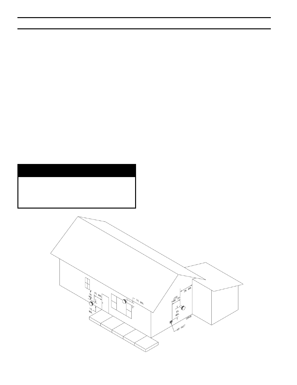
5. Locate the vent terminal so vent pipe is short and
direct, and at a place on the exterior wall that
complies with the minimum distances as specified in
Figure 8 and listed below. The vent terminal must
be located:
a. Not less than 12 inches above grade plus snow
accumulation (as measured to the nearest edge of
terminal).
b. Not less than 3 feet to center of terminal above
any forced air inlet located within 10 feet.
c. Not less than 1 foot to center of terminal
horizontally from any door, window or gravity
air inlet.
d. Not less than 7 feet to center of terminal above a
public walkway.
e. Not less than 3 feet to center of terminal from an
inside corner of an L-shaped structure.
f. Not less than 1 foot from nearest surface of
terminal to a roof soffit.
g. Not directly above, or not less than 6 feet
horizontally from an oil tank vent or gas meter.
h. Not less than 2 feet from nearest surface of
terminal to an adjacent building.
Figure 8: Vent Terminal Location